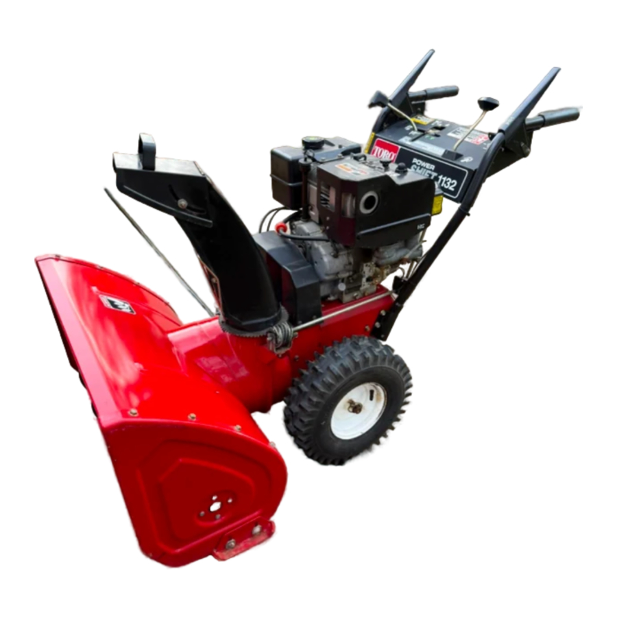
Toro 828, 1132, 38570, 38580 Manual
SAFETY INSTRUCTIONS
The 828 and 1132 POWER SHIFT SNOWTHROWERS meet or exceed the Outdoor Power Equipment Institute's safety standards for snowthrowers; thus, Toro proudly displays the OPEI safety seal. To assure maximum safety, optimum performance, and to gain knowledge Of the product, it is essential that you or any other operator of the snowthrower read and understand the contents of this manual before the engine is ever started. Pay particular attention to the safety symbol which means CAUTION, WARNING or DANGER —"personal safety instruction". Read and understand the instruction because it has to do with safety.
Failure to comply with the instructions may result in personal injury.
The following instructions are comparable to the Instructions For Safety Snowthrowing adopted by ANSI — American National Standards Institute. The snowthrower is designed and tested to offer reasonably safe service: however, failure to operate it in accordance with the following Safety Instructions MAY RESULT IN PERSONAL INJURY.
BEFORE OPERATING
- Read and understand the contents of this manual before starting and operating the machine. Become familiar with all controls and know how to stop the engine quickly.
- Keep everyone, especially children and pets, away from the area of operation. Never allow children to operate the snowthrower.
- Inspect area thoroughly where snowthrower will be used. Remove door mats, sleds, boards, sticks. wire and any other foreign objects which might be picked up and thrown by the snowthrower.
- Keep all shields and safety devices in place. If a shield, safety device or decal is defective or damaged, repair or replace it before operation is commenced. Also, tighten any loose nuts, bolts and screws.
- Wear adequate winter clothing and footwear that will improve footing on slippery surfaces. Do not wear loose fitting clothing that could possibly get caught in moving parts.
- Adjust both skids so auger housing clears gravel or crushed rock surfaces.
- Before starting the engine, move speed control to N (neutral).
- Always use a grounded three wire plug and cord to start snowthrower equipped with an electric starter.
- Fill fuel tank with gasoline before starting the engine. Avoid spilling any gasoline. Since gasoline is highly flammable, handle it carefully. DO NOT SMOKE WHILE HANDLiNG GASOLINE.
- Use an approved gasoline container.
- Fill fuel tank outdoors and only when engine is not running. Engine must be cool to prevent a potential fire hazard.
- Open doors if engine will be run in the garage because exhaust fumes are dangerous and could possibly be deadly. Do not run engine indoors.
- Wipe up any gasoline that spilled, and install gasoline container cap and snowthrower fuel tank cap securely before starting the engine.
WHILE OPERATING
- STAY BEHIND THE HANDLES AND AWAY FROM DISCHARGE OPENING WHILE OPERATING THE SNOWTHROWER. Keep face, hands, feet and any other part of your body or clothing away from concealed, moving or rotating parts.
- BEFORE ADJUSTING, CLEANING, REPAIRING AND INSPECTING THE SNOWTHROWER, AND BEFORE UNCLOGGING THE DISCHARGE CHUTE. SHUT ENGINE OFF AND WAIT FOR ALL MOVING PARTS TO STOP. ALSO, PULL WIRE OFF SPARK PLUG AND KEEP WIRE AWAY FROM THE PLUG TO PREVENT ACCIDENTAL STARTING. USE A STICK TO REMOVE OBSTRUCTIONS.
- Keep people and pets a safe distance away from the snowthrower and area Of operation.
- Allow engine to warm up for about 2 minutes and machine to adjust to outdoor temperature before clearing snow.
- Do not run engine indoors, except when starting engine. When starting engine indoors, open outside doors because exhaust gasses are dangerous.
- Operate the snowthrower only when there is good visibility or light. Always maintain secure footing and keep a firm grip on the handles, especially when operating in reverse.
- Be attentive when using the snowthrower, and stay alert for holes in the terrain and other hidden hazards. Be careful when clearing snow from a gravel drive because stones could be picked up and thrown if the skids are not adjusted so auger housing clears all rocks.
- Do not make any adjustments while the engine is running.
- Never direct discharge of snow or operate snowthrower near bystanders. glass enclosures, automobiles and trucks, window wells or a dropoff without proper adjustment of the snow discharge angle.
- Clear snow from slopes by going up and down; never across the face, and use caution when changing directions. use lower gear and rear wheel position when operating on slopes. Never clear snow from steep slopes.
- Do not overload the snowthrower by clearing snow at too fast a rate.
- If a solid object is hit or snowthrower vibrates abnormally, shut engine off and wait for all movement to stop. Pull high tension wire off spark plug and check snowthrower immediately for possible damage, an obstruction or loose parts. Vibration is generally a warning of trouble. Repair any damage before restarting engine and operating snowthrower again.
- Do not touch engine while it is running or soon after it is stopped because the engine will be hot enough to cause a burn. Do not add oil or check oil level in crankcase when engine is running because this could be a potential hazard.
- Before leaving the operator's position — behind handles — rotate ignition key to OFF. Remove key from switch if snowthrower will be left unattended.
- Never operate snowthrower at high transport speeds on slippery surfaces. Use care when backing.
- Let engine run for a few minutes after clearing snow so moving parts do not freeze.
MAINTAINING SNOWTHROWER
- Perform only those maintenance instructions described in this manual. Shut engine off before performing any maintenance service or adjustment. Additionally, pull high tension wire off spark plug and keep wire away from plug to prevent possibility of accidental starting. If major repairs are ever needed, contact the local Authorized TORO Service Dealer for assistance.
- Keep snowthrower in safe operating condition by keeping nuts, bolts and screws tight. Check engine mounting bolts frequently to assure they are tight.
- Do not overspeed the engine by changing governor settings. Recommended maximum engine speed is 3500 rpm. To assure safety and accuracy, check maximum engine speed (3500 rpm) with a tachometer.
- Allow engine to cool before storing snowthrower in an enclosure such as a garage or storage shed, and make sure the snowthrower fuel tank is empty. Do not store snowthrower near any open flame or where gasoline fumes may be ignited by a spark.
- When storing the snowthrower for an extended time — off season storage or 30 days — drain gasoline from fuel tank to prevent a potential hazard. Store gasoline in a safetyapproved red metal container. Remove key from ignition switch and keep it in a memorable place.
- At the time of manufacture, the snowthrower conformed with and exceeded safety standards in effect for snowthrowers. Therefore, to assure optimum performance and safety, purchase genuine TORO replacement parts and accessories to keep the TORO all TORO. NEVER USE "WILL-FIT" REPLACEMENT PARTS AND ACCESSORIES. The TORO logo assures genuineness.
- For safety reasons, use only those accessories and attachments recommended by The TORO Company to assure continued safety certification of the product. using unapproved accessories and attachments could contribute to a potential hazard.
SAFETY DECALS
Safety and instruction decals are located on the snow thrower chassis and engine. Replace any decal that is damaged.


LOOSE PARTS

Specifications and design subject to change without notice.
SETTING UP INSTRUCTIONS
 Note: Determine left and right sides of snowthrower by standing in the normal operating position.
MOUNT AUGER HOUSING (Fig. 1-3)
- Remove (2) flange head capscrews securing idler pulley assembly to engine frame. Remove idler pulley assembly.
- Align auger housing and engine frame mounting holes (Fig. 1).


- Auger housing
- Engine frame
- Impeller pulley
- Idler pulley assembly
- Mounting screws (2)
- Route impeller belt around impeller pulley.
- Secure auger housing to engine frame with (6) 5/16-18 x 5/8" lg. flange head capscrews.


- Lower belt cover (shown from bottom'
- Mounting tabs
- Reinstall idler pulley assembly. Make sure idler pulleys are aligned with belts when reinstalling idler pulley assembly.
- Tip snowthrower up on auger housing.
- Mount lower belt cover to underside of auger housing and engine frame with (2) 1/4-20 x 1/2" lg. flange head capscrews (Fig. 2). Make sure belt cover mounting tabs are positioned to rear of engine frame member.
- Mount upper belt cover to engine frame with (3) 1/4-20 x 1/2" lg. flange head capscrews (Fig. 3).
- Slide cable cover onto cables and into hole in belt cover.

- Upper belt cover
- Cable cover
INSTALL SHIFT ROD (Fig. 4)

- Shift rod
- Ball joint
- Shift bracket
- Transmission lever
- Locknut
- Jam nut
- Gear shift lever
- Power shift slot
- Insert upper shift rod ball joint stud thru front of shift bracket and secure with 3/8-24 locknut.
- Insert bottom ball joint stud thru right side Of transmission lever and secure with 3/8-24 locknut.
Note: If gear shift lever is not aligned with Power Shift slot in control panel (Fig. 4, Inset), shift rod length must be adjusted as follows:
- Disconnect ball joint from transmission lever and loosen jam nut.
- Rotate ball joint up or down, until gear shift lever is aligned with power shift slot.
- Reinstall ball joint to transmission lever and tighten jam nut.
INSTALL DISCHARGE CHUTE (Fig. 5)

- Discharge chute
- Plastic chute retainer
- Chute retainer plate
- Set discharge chute — open side forward — onto auger discharge opening, so plastic chute retainers are positioned on chute ring. Make sure chute retainer guide pins are inserted into holes in chute gear.
- Tighten left hand machine screw and locknut until chute retainer plate is positioned against plastic chute retainer and discharge chute is secured to chute ring.
- Push right hand chute retainers toward discharge chute (slotted) and tighten machine screw.
- Make sure chute rotates freely ring. Move right hand retainer (slotted) outward to ease operation.
INSTALL CHUTE CONTROL GEAR (Fig. 6)

- Gear bracket
- Carnage bolt, flat-washer & locknut
- Worm gear
- Chute gear rod
- Insert the 5/16-18 x 1" lg. carriage bolt into gear bracket mounting hole.
- Position worm gear into bracket, align holes and insert chute gear rod through bracket and gear.
- Loosely mount worm gear and bracket to mounting flange with flat washer and locknut.
- Slide worm gear into teeth of chute gear and tighten locknut.
- Check operation, move gear slightly outward if binding is evident.
CHECK TIRE PRESSURE

Check pressure of tires because they are over inflated at the factory for shipping. Therefore, before the snowthrower is operated, reduce pressure in both tires to 10-15 psi equally.
CHECK AUGER GEAR BOX OIL (Fig. 7)

- Pipe plug
- Move snowthrower to a level surface.
- Remove pipe plug from gear box.
- Check level Of oil in gear box. Oil must be at point of overflowing in filler opening.
- If level of oil is low, add GL-5 or GL-6 SAE 85-95 EP transmission Oil to the gear box until point of overflow.
- Install pipe plug in gear box.
PREPARATION BEFORE STARTING
FILL CRANKCASE WITH OIL (Fig. 8)

- Dipstick
- Filler Hole
The engine is shipped from the factory without oil in the crankcase. Therefore, before trying to start engine, oil must be added to the crankcase.
Check level of oil every 5 operating hours or each time unit is used. Initially, change oil after the first 2 hours of operation: thereafter. under normal conditions, change oil after every 25 hours of operation or annually.
- Move unit to a level surface to assure an accurate oil level reading.
- Clean area around dipstick to prevent foreign matter from entering filler hole when dipstick is removed.
- Remove dipstick from crankcase.
- Slowly, pour SAE 5W-30 or SAE 10 oil into the filler hole, using Oil filler chart below. The engine uses any high-quality detergent oil having the American Petroleum Institute — API — "Service classification" SE or SF.
Oil Fill Chart
828 Snowthrower 44 ounces of oil
1132 Snowthrower 48 ounces of oil
Note: Dipstick must be fully installed to assure accurate gauging of oil level, DO NOT OVERFILL FILL FUEL TANK WITH GASOLINE.
THE TORO COMPANY STRONGLY RECOM-MENDS THE USE OF CLEAN, FRESH UNLEADED REGULAR GASOLINE IN TORO GASOLINE POWERED PRODUCTS. UNLEADED GASOLINE BURNS CLEANER, EXTENDS ENGINE LIFE, AND PROMOTES GOOD STARTING BY REDUCING THE BUILDUP OF COMBUSTION CHAMBER DEPOSITS. LEADED GASOLINE CAN BE USED IF UNLEADED IS NOT AVAILABLE.

Because gasoline is flammable, caution must be used when storing or handling it. Do not fill fuel tank while engine is running, hot or when unit is in an enclosed area. Keep away from open flame and electrical spark. and DO NOT SMOKE while filling the fuel tank to prevent the possibility of an explosion. Always fill fuel tank outside and wipe up any spilled gasoline before starting engine. Use a funnel or spout to prevent spilling gasoline, and fill fuel tank to about 1/2 inch (13 mm) from the top Of the tank, not the filler neck.
Store gasoline in a clean, approved container and keep the cap in place on the container. Keep gasoline in a cool, well-ventilated place; never in the house. To assure volatility, do not buy more than a 30 day supply of gasoline. Gasoline is a fuel for internal combustion engines: therefore, do not use it for any other purpose. Since many children like the smell of gasoline, keep it out of their reach because the fumes are explosive and dangerous to inhale.
NOTE: NEVER USE METHANOL, GASOLINE CONTAINING METHANOL. GASOHOL CONTAINING MORE THAN 10% ETHANOL. GASOLINE ADDITIVES. PREMIUM GASOLINE. OR WHITE GAS BECAUSE ENGINE FUEL SYSTEM DAMAGE COULD RESULT.
- Clean area around the fuel tank cap. Remove cap from fuel tank and fill tank to within 1/2" (13 mm) from the top with unleaded regular gasoline. Reinstall fuel tank cap. Fuel tank capacity is 4 quarts.
CONTROLS
Auger/impeller Control (Fig. 9) — Control has two positions: ENGAGE and DISENGAGE. To engage auger and impeller, compress lever against right handle grip. TO disengage, release lever.
Traction Drive Control (Fig. 9) — To engage traction or activate power shift system, lever must be compressed against left handle grip. TO stop traction, release lever.
Speed Shift Control (Fig. 9) — The control has four speeds forward and two reverse and also controls power shifting of wheels. To select speeds, move shift control to desired position.
Note: Release traction drive control when shifting to change speeds or to Power Shift.
Auger Lock-Up: (Fig. 9) — When auger/impeller control and traction drive control are both compressed, the traction control locks the auger/impeller control down. Releasing the traction control releases the auger/impeller.

- Auger/impeller control
- Traction drive control
- Speed shift control
- Ignition switch
- Discharge chute control
Discharge Chute Control (Fig. 9) — Rotate discharge chute control clockwise to move discharge chute to the right and counterclockwise to move chute to the left.
Ignition Switch (Fig. 9) — Switch has two positions: ON and OFF. Rotate key to ON position before starting engine. To stop engine, rotate key to OFF.
Throttle (Fig. 10) — Moving the throttle upward increases the engine speed.
Choke (Fig. 10) — Choke is located on left side of engine. Push choke down to FULL choke position to start a cold engine. As engine warms up, move choke gradually to OFF.

- Throttle
- Choke
- Primer
Primer (Fig. 10) — Press primer to pump small amount of gasoline into engine for improved cold weather starting.

- Fuel shut-off valve
Fuel Shut-Off Valve (Fig. 11) — Valve is located under fuel tank. Close valve to stop fuel flow from fuel tank and open valve to allow fuel to flow to the carburetor. Close valve when snowthrower is not used.
Deflector Handle — Deflector handle on top Of discharge chute is used to control the height of the snow stream.
Recoil Starter (Fig. 12) — Recoil starter is on back side of engine. Pull recoil starter to start engine.

- Recoil starter
STARTING AND STOPPING INSTRUCTIONS
Check auger and impeller to assure that both parts are not frozen solid, but free to rotate. Also. make sure discharge chute is not obstructed.
- Move speed selector to N — neutral — and throttle to FAST (Fig. 9).
- Open fuel shut-off valve below fuel tank.
- Move choke to full choke position (Fig. 10).
- Rotate ignition key to ON (Fig. 9).
- Depress primer (Fig. 10) five times.
- Grasp recoil starter handle (Fig. 12) and pull it out slowly until positive engagement results; then pull vigorously to start the engine Keep firm grip on starter handle and return the rope slowly.
![information]() Note: If engine does not start or if temperature is —10 F or below, additional priming may be required.
Note: If engine does not start or if temperature is —10 F or below, additional priming may be required.
- After engine Starts, immediately move choke (Fig. 10) to 3/4 position. As engine warms up, move choke to 1/2 position; then to OFF position. If engine falters, return choke to 1/2 position. When engine warms sufficiently, move choke to OFF position.
BEFORE STOPPING ENGINE
- Run engine for a few minutes to help dry off any moisture which may have accumulated on engine.
TO STOP ENGINE:
- Release traction and auger/impeller drive controls (Fig. 9).
- Move speed selector to N — neutral.
- Move throttle to slow and rotate ignition key to OFF.
OPERATING INSTRUCTIONS
POWER SHIFT OPERATION
Move wheels rearward to the Power Shift position in heavy and/or drifted snow. Leave wheels in the front position for light snow or for transporting snowthrower.
- Release traction drive lever.
- To move wheels to front or rear position, move shift control fully forward to Power Shift position and hold (Fig. 13).

- Fully engage traction drive lever to move wheels into Power Shift position (Figs. 13&14).
![information]() Note: When power shifting it may be necessary to slightly raise handles to assist wheel movement.
Note: When power shifting it may be necessary to slightly raise handles to assist wheel movement.


Note: If wheels do not move in desired direction when power shifting, repeat procedure. Wheels must rotate in forward direction to move wheels aheadand rotate rearward to move wheels back.
FREE WHEELING OR SELF PROPELLED DRIVE
The snowthrower can be free wheeled or engaged for self propelled operation. When axle pins are through outer axle holes (Fig. 15), snowthrower will free wheel. By contrast, when both pins are installed through holes in wheel hub and inner hole of axle (Fig. 15), snowthrower will self propel itself.

- Axle pin
SNOWTHROWING TIPS
- When snowthrower is not being used, close fuel shut-off valve, have speed control in N — neutral position, and key removed from the switch.
- Remove snow as soon as possible after it falls. This will produce best snow removal results.
- When in the Power Shift position, pushdown on handles to increase traction.
- If snow will be removed from crushed rock or gravel areas, adjust skids so bottom Of auger housing clears the rocks: refer to Adjusting Skids.
- For concrete or asphalt surfaces, adjust skids so there is 1/8 inch (3 mm) between bottom Of auger and concrete or asphalt surface.
- Discharge snow downwind whenever possible, and overlap each swath to assure complete snow removal. If wheels slip, shift into a lower gear which reduces forward speed.
- In some snow and cold weather conditions, some controls and moving parts may freeze solid. Therefore, when any control becomes hard to operate, stop the engine; then check all parts for freezeup. DO NOT USE EXCESSIVE FORCE AND TRY TO OPERATE THE CONTROLS WHEN FROZEN. Freeall controls and moving parts before operating.
(Fig. 16)

- Flange screws
When snowthrower will be used on concrete or asphalt surfaces, adjust skids using steps 1 - 2. However, use only step 3 when snowthrower will be used on gravel or crushed rock surfaces.
- Move snowthrower to a level surface. Next, loosen four flange screws securing both skids to auger side plates. Skids must slide up and down.
- Adjust both skids so there is 1/8 of an inch between bottom of auger and level surface. When skids are adjusted correctly, tighten flange nuts. Next, check scraper blade that is mounted at bottom of auger housing. Scraper must be parallel with level surface. If scraper is not parallel, adjust skids again. Do not use step 3 after adjusting skids for hard surfaces.
- Loosen four flange screws securing both skids to auger side plates. Next, slide skids down as far as possible so auger is as far from the level surface as skid adjustment allows; then tighten flange screws.
MAINTENANCE
TO prevent accidental starting of the engine while performing maintenance, rotate the ignition key to off and remove it from the switch. Next, pull wire off spark plug and make sure wire does not accidentally touch the plug.
DRAINING GASOLINE
- Close fuel shut off valve located under engine (Fig. 17).
- Place a clean drain pan under shut off valve.
Since gasoline is highly flammable. drain it outdoors and make sure engine is cool to prevent a potential fire hazard. Wipe up any gasoline that may have spilled. DO not drain gasoline near any open flame or where gasoline fumes may be ignited by a spark. Do not smoke a cigar. cigarette, or a pipe when handling gasoline.

- Fuel shut off valve
- Hose clamp
- Fuel line
- Loosen hose clamps securing fuel line to valve and slide line off valve (Fig. 18).
- Open valve allowing fuel to flow into drain pan.
- Reinstall fuel line and secure with hose clamp.
LUBRICATING SNOWTHROWER
- Annually, lubricate drive chain with chain lubricant (Fig. 18). Wipe up any excess oil.

- Drive chain

CHANGING CRANKCASE OIL (Fig. 19)

- Drain cap
Initially, change oil after the first 2 hours of engine operation; thereafter, change oil after every 25 hours of engine operation or annually. If possible, run engine just before changing oil because warm oil flows better and carries more contaminants than cold oil.
- Pull wire off spark plug and make sure wire does not contact plug accidentally.
- Clean area around oil drain cap. Next, slide oil drain pan below drain extension; then remove Oil drain cap.
- After all oil is drained, install oil drain cap.
- Position snowthrower on a level surface. Next, fill crankcase with oil: see Fill Crankcase With Oil. Wipe up any oil that may have spilled.
AUGER GEAR BOX OIL (Fig. 20)

- Pipe plug
The auger gear box is filled with oil at the factory so regular maintenance is not required. However, if oil must be replacedin gear box:
- Drain gasoline from fuel tank. Wipe up any spilled gas.
- Position snowthrower on a level surface.
- Clean area around pipe plug so dirt is removed.
- Put a drain pan below front of auger gear box and remove pipe plug: refer to Check Auger Gear Box Oil.
- Tips now thrower forward and hold it up until all oil drains from the gear box.
- Carefully let snowthrower down to its normal position. Make sure it is on a level surface. Next, fill auger gear box with GL-5 or GL-6 SAE 85-95 EP transmission oil to the point of overflow.
- Install pipe plug in gear box.
ADJUSTING AUGER/IMPELLER DRIVE BELT (Figs. 21-22)
If auger/impeller belt slips, resulting in decreased snowthrowing performance, an adjustment is required. WHENEVER A NEW BELT IS INSTALLED, AN ADJUSTMENT IS REQUIRED.
- Remove (3) flange head capscrews securing belt cover to engine frame and slide belt cover up cables.
- Check idler and brake adjustment. There should be a minimum clearance of 1/8" between tab on impeller idler arm and brake arm (Fig. 22). If there is less than 1/8" clearance, belt must be replaced.
- Loosen upper jam nut securing auger/impeller cable to mounting bracket (Fig. 21).

- Auger/impel/er cable
- Traction cable
- Mounting bracket
- Rotate bottom jam nut upward to increase belt tension.
Note: When adjusting cable, always rotate nut one turn at a time.
Do not adjust the belt too tight because it may cause the auger/impeller to turn when the auger/impeller is in the disengaged position. If this occurs, readjust, loosening belt tension.
- Tighten upper jam nut against bracket.

Improper adjustment may cause injury if auger/impeller turns when disengaged. Use only genuine Toro replacement parts.

- Idler arm
- Brake arm
- Recheck idler and brake adjustment, refer to step #2
- Reinstall belt cover.
- Check tension of belt by operating the auger. If belt slips, repeat procedure
ADJUSTING TRACTION DRIVE BELT (Fig. 21)
If the traction belt slips during operation, and adjustment is required. Whenever the belt is replaced, an adjustment is required.
- Loosen upper jam nut securing traction cable to mounting bracket
- Rotate bottom jam nut upward to increase tension.
Note: When adjusting cable, always rotate nut one turn at a time.
- Tighten upper jam nut against bracket.
Check tension of belt by operating machine. If belt still slips, repeat procedure.
Do not adjust the belt too tight because it may cause snowthrower to creep when traction lever is in disengaged position. If this occurs, readjust, loosening belt tension.
REPLACING DRIVE BELTS (Fig. 23)

- Idler pulley assembly
- Mounting screws (2)
- Capscrew & lockwasher
- Half sheave
- Auger/impeller belt
- Traction belt
If auger/impeller belt or traction belt become worn, glazed, stretched, oil-soaked, or otherwise defective, belt replacement is required.
- Pull wire Off spark plug and make sure it does not contact the plug accidentally.
- Remove (3) thread forming screws holding belt cover in place, and slide belt cover up cables.
- Move speed shift control to N, neutral.
- Remove (2) flange head capscrews securing idler pulley assembly to engine frame. Remove idler pulley assembly.
- Remove capscrew and lock washer securing half sheave to front of pulley assembly.
- Slide auger/impeller pulley and belt off crankshaft and remove belt from impeller pulley.
- If replacing traction belt, slide traction pulley and belt off crankshaft and remove belt from transmission pulley.
- On control cable which corresponds to belt being replaced, loosen jam nuts securing cable to bracket (Fig. 21). Cable must be free to slide in bracket when changing belt (s).
- Reinstall belts by reversing procedure. Make sure tabs in half sheave are inserted into mounting grooves in auger/impeller pulley when reinstalling.
Note: Make sure idler pulleys are aligned with belts when reinstalling idler pulley assembly.
- Readjust belts, refer to Adjusting Auger/ Impeller Drive Belt or Adjusting Traction Drive Belt.
Improper adjustment may cause injury if auger/impeller turns when disengaged. Use only genuine Toro replacement parts.
ADJUSTING DRIVE CHAIN (Figs. 24-27)
The drive chain must be adjusted to maintain 1/8-3/8 of an inch deflection at mid span between transmission and axle sprocket. Check chain deflection after every 25 hours of operation.
- Check deflection of chain by lifting up on chain with moderate pressure at mid span. There should be 1/8-3/8" deflection. If deflection is not as specified an adjustment is required.


TO adjust drive chain, the snowthrower must be tipped up on auger housing. However, before the snowthrower is tipped, drain all gasoline from fuel tank.
- Make sure wheels are positioned in rearposition, move shift controlin to 2nd gear and tip snowthrower up onto auger housing.

- Transmission
- Transmission frame
- Loosen (4) flange headcapscrews (2 each side) securing transmission frame to engine frame (Fig. 26).
- Lightly lift up on transmission frame until 1/8-3/8" chain deflection is attained, then, retighten flangehead capscrews.

- Flange head cap screws
Do not pry or use excessive force when lifting transmission frame, as transmission damage may occur.
Note: If gear shift lever is not aligned with Power Shift slot in control panel (Fig. 27 inset), shift rod length must be adjusted as follows:

- Shift rod
- Ball joint
- Shift bracket
- Transmission lever
- Locknut
- Jam nut
- Gear shift lever
- Disconnect ball joint from transmission lever and loosen jam nut.
- Rotate ball joint up or down, until gear shift lever is aligned with Power Shift slot.
- Reinstall ball joint to transmission lever and tighten jam nut.
- Recheck chain deflection and lower snow thrower to normal position.
REPLACING SPARK PLUG (Fig. 28)

Correct spark plug to use is a Champion RCJ-8 or Autolite AR7N, and correct air gap is 0. 030 of an inch (0. 76 mm). Since air gap between center and side electrodes of the spark plug increases gradually during normal engine operation, install a new plug after every 25 hours Of engine operation.
- Clean area around spark plug so foreign matter cannot fall into cylinder when plug is removed.
- Pull wire off spark plug and remove plug from cylinder head.
A cracked, fouled. or dirty spark plug must be replaced. Do not sand blast. scrape. or clean electrodes because grit may eventually release from plug and fall into the cylinder. The result will likely be engine damage.
- Set air gap between electrodes of new spark plug at 0. 030 of an inch (0. 76 mm) (Fig. 28). Next, install spark plug in cylinder head. Tighten plug to 15 ft-lb (20. 4 N-m). If torque wrench is not used, tighten plug firmly.
- Push the wire onto spark plug.
ADJUSTING CARBURETOR (Fig. 29)

- Needle valve
- Idle valve
- Idle speed adjusting screw
The carburetor has been adjusted at the factory, but an occassional adjustment may be required.
- Needle Valve — Close needle valve finger-tight by gently rotating it clockwise.
Do not close needle valve too tight because valve and seat in carburetor will likely be damaged.
- Rotate — open — needle valve 1-1/2 turns counterclockwise.
- Idle Valve — Close idle valve finger-tight by gently rotating it clockwise.
![]()
Do not close idle valve too tight because valve and seat in carburetor will likely be damaged. - Rotate — open — idle valve 1/4 turn to 3/4 Of a turn counterclockwise. Note: The needle valve and idle valve settings are approximates; however the settings will allow engine to be started so carburetor can be fine tuned — steps 5 - 11.
Engine must be running so final adjustment of the carburetor can be performed. To guard against possible personal injury, move auger drive and wheel drive controls to DISENGAGE, and remember to keep hands, feet, face, and othe rparts of the bodyaway from muffler. auger, discharge chute, and any moving part (s).
- Start engine and let it warm up for approximately two to three minutes; then move throttle to FAST.
- Rotate needle valve clockwise — in — until engine misses because of a lean gasoline mixture. Then rotate needle valve counterclockwise —out— so engine runs unevenly because of a rich gasoline mixture. Next, rotate needle valve clock-wise, back to the midpoint between the rich and lean setting so engine runs smoothly.
- Move throttle control backward to idle speed. Rotate idle speed adjusting screw until engine idles fast — 1750 rpm.
- Rotate idle valve clockwise — in — until engine begins to miss because Of a lean mixture. Then rotate idle valve counterclockwise —out — until engine runs unevenly because of rich mixture. Next, rotate idle valve clockwise, back to the mid-point between rich and lean setting.
- Again rotate idle speed adjusting screw until engine idles at 1750 rpm.
- Check carburetor adjustment by quickly moving throttle from idle speedto high speed. Engine should accelerate without hesitation or sputtering. If engine does not accelerate properly, adjust carburetor to a slightly richer mixture,
- After carburetor is adjusted shut engine off.
PREPARING SNOWTHROWER FOR STORAGE
- Drain gasoline from fuel tank: refe rto Draining Gasoline. Wipe up any gasoline that may have spilled.
- Start the engine and let it run until it stops because there is no gasoline in the fuel system.
- Remove spark plug from cylinder head. Next, pour two teaspoons of engine Oil into spark plug hole in cylinder head. Install spark plug in cylinder héad, but do not instäff wire on the plug. Then pull recoil starter slowly to distributeoil on inside of cylinder.
- Lubricatethe snowthrower: referto Lubricating Snowthrower. Change crankcase oil: see Changing Crankcase Oil.
- Clean the snowthrower. Touch up chipped surfaces with paint. Sand affected areas before painting, and use a rust preventative to prevent metal parts from rusting.
- Tighten all screws and nuts. If any part is damaged, repair or replace it.
- Store snowthrower in a clean, dry place, and cover it to give protection.
- The snowthrower may be stored in upright position. Make sure to drain gas before tipping snowthrower up right on auger housing.
IDENTIFICATION AND ORDERING
MODEL AND SERIAL NUMBERS
The snowthrower has two identification numbers: a model number and a serial number. The two numbers are stamped on a decal which is located on back of engine mounting plate. In any correspondence concerning the snowthrower, supply model and serial numbers to assure that correct information and replacement parts are obtained.
To order replacement parts from an Authorized TORO Service Dealer, supply the following information:
- Model and serial numbers of the snow thrower.
- Part number, description, and quantity of part (s) desired.
![information]() Note: DO not order by reference number if aparts catalog is being used; use the PART NUMBER.
Note: DO not order by reference number if aparts catalog is being used; use the PART NUMBER.
Download manual
Here you can download full pdf version of manual, it may contain additional safety instructions, warranty information, FCC rules, etc.
Download Toro 828, 1132, 38570, 38580 Manual


