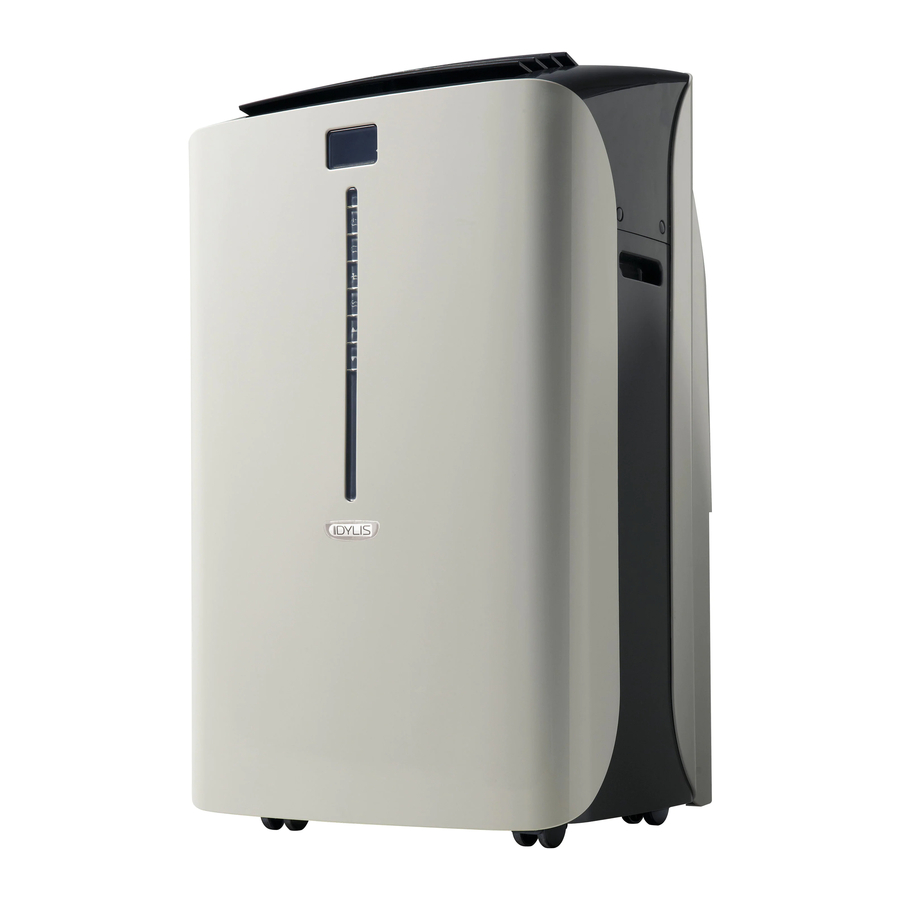
Idylis Portable Air Conditioner 416709 Manual
PACKAGE CONTENTS


| PART | DESCRIPTION | QUANTITY |
| A | Air Outlet | 1 |
| B | Control Panel | 1 |
| C | Castor | 4 |
| D | Handle Hole | 1 |
| E | Water Outlet Drain | 1 |
| F | Air Outlet | 1 |
| G | Power Supply Cord | 1 |
| H | Water Outlet Drain | 1 |
| I | Air Intake (Condensor) | 1 |
| J | Air Intake (Evaporator) | 1 |
| K | Air Filter | 1 |


| PART | DESCRIPTION | QUANTITY |
| L | Flexible Exhaust Hose | 1 |
| M | Exhaust Nozzle Connector | 2 |
| N | Tube Adapter | 1 |
| O | Screw | 4 |
| P | Window Panel Extension | 1 |
| Q | Window Panel | 1 |
| R | Drain hose | 1 |
| S | AAA Batteries | 2 |
| T | Remote | 1 |
 SAFETY INFORMATION
Please read and understand this entire manual before attempting to assemble, operate or install the product.
Portable air conditioners exhaust large amounts of room air. Always ensure an adequate supply of make-up air to operate effi ciently.
- Check available power supply and resolve any wiring problems BEFORE installation and operation of this unit. All wiring must comply with local and national electrical codes and be installed by a qualifi ed electrician. If you have any questions regarding the following instructions, contact a qualifi ed electrician.
- This appliance draws 9.5 nameplate amps and may be used in any properly wired general purpose 15 amp household grounded receptacle.
- For your safety and protection, this unit is grounded through the power cord plug when plugged into a matching wall outlet. If you are not sure whether the wall outlets in your home are properly grounded, consult a qualifi ed electrician.

- Do not leave this unit unattended in a space where people or animals that cannot react to a failed unit are located. A failed unit can cause extreme overheating or death in such an enclosed, unattended space.

- Improper connection of the grounding plug can result in risk of fi re, electric shock, and/or injury to persons associated with the appliance. Check with a qualifi ed service representative if in doubt that the appliance is properly grounded.
- DO NOT USE PLUG ADAPTERS OR EXTENSION CORDS WITH THIS UNIT. If it is necessary to use an extension cord with this unit, use an approved "air conditioner" extension cord only.
- To avoid the possibility of personal injury, always disconnect the power supply to the unit before installing and/or servicing.
POWER SUPPLY CORD
The power cord supplied with this air conditioner contains a device that senses damage to the power cord. To test if your power cord is working properly, you must do the following:
- Connect the power supply cord to an electrical outlet.
- The power supply cord has two buttons located on the head of the plug. One button is marked "TEST" and the other is marked "RESET." Press the "TEST" button; you will hear a click as the "RESET" button pops out.
- Press the "RESET" button; you will hear a click as the button engages.
- The power supply cord is now energized and supplying electricity to the air conditioner (on some products this is also indicated by a light on the plug head.)
- Note: The power cord supplied with this air conditioner contains a current leakage detection device designed to reduce the risk of fi re. In the event the power supply cord is damaged, it cannot be repaired and must be replaced with a new cord from the product manufacturer.
- Under no circumstance should this device be used to turn the unit on or off.
- The reset button must always be pushed in (engaged) for correct operation.
- The power supply cord must be replaced if it fails to reset when the "TEST" button is pushed in.
PREPARATION
Before beginning assembly of product, make sure all parts are present. Compare parts with package contents list. If any part is missing or damaged, do not attempt to assemble the product.
Estimated Assembly Time: 20 minutes
Tools Required for Assembly (not included): Phillips Screwdriver
ASSEMBLY INSTRUCTIONS
- Insert tube adapter (M) through the back of the hole in the window panel (P).

- Using the 4 screws (N) supplied, secure the tube adapter (M) from the front of the window panel (P).

Hardware Used

- Insert window panel extension (O) into the window panel (P). Lightly tighten the pre-assembled screws in the window panel (P) to hold the extension (O) in place.

- Select a suitable location for the unit, making sure you have access to an electrical outlet.

- Install the window panel (P) by expanding it to fit the length of the window and fully tightening the pre-assembled screws in the middle.

- Attach an exhaust nozzle connector (L) to each side of the exhaust hose (K). Then, install one end of the exhaust hose (K) to the air oulet (F) on the rear side of the unit, and the other end of the exhaust hose into the opening in the window panel (P). The minimum length of the exhaust hose is 21-13/20 in. and the maximum length is 66-3/20 in. when fully extended.

- Plug the unit into a 115V/60Hz grounded electrical outlet.


OPERATING INSTRUCTIONS
Features of the Control Panel:
Keypad Functions

- Power switch: Turns unit on/off
- Mode: Allows you to scroll through desired operating modes
- Fan: Select from three different fan settings: high, medium, and low.
- Auto timer
- Up/down buttons: By pressing both
![]() and
and ![]() buttons at the same time for more than 3 seconds, the display will toggle between Celsius and Fahrenheit.
buttons at the same time for more than 3 seconds, the display will toggle between Celsius and Fahrenheit.
LCD Display Note: The default display is room temperature

 Cooling Mode
 Dehumidify Mode
 Fan Only Mode
 High Fan Speed
 Medium Fan Speed
 Low Fan Speed
 Display Set Temperature
 Display Auto-timer On/Off Setting
 Warning Light (the machine will stop running)
Warning light: Condensed water may accumulate in the unit. If the internal tank becomes full, the warning signal in the LCD display will light up and the unit will not operate until it has been drained.
Note: After turning the unit off, it is necessary to wait 3 minutes before turning it back on again.
AIR CONDITIONING
Note: The exhaust hose must be properly vented outdoors during air conditioning mode.
- Press the POWER SWITCH button to switch on the unit, and the most recent set temperature will be shown in the temperature display area of the control panel.
![]()
- Press the MODE button until the COOL indicator light illuminates on the control panel. Each depression of the MODE button will advance to a different mode setting (Cool - Dehumidifier - Fan)
![]()
- Press the appropriate increase or decrease buttons to select a suitable operating temperature setting. Temperature settings are adjustable between 16°C (61°F) to 32°C (89°F.)
![]()
- Press the FAN button to select the desired fan speed setting (High-Med-Low.) Your selection will appear on the control panel (each depression of the fan key will advance to a different setting.)
![]()


Cooling stops automatically when the set temperature is achieved. Cooling resumes when the room temperature rises above the 'set' temperature level.
DRAINING EXCESS WATER
If the water tank in the unit becomes full, a 'full tank' indicator light will come on. To drain excess water:
- Begin by placing a pan under the water outlet drain (E).

- Unscrew the drain cover and remove the soft rubber stopper. Let the water drain into the pan. When the water stops draining out, replace the soft rubber stopper and tighten the drain cover.

- Remove the pan of water and empty into a sink.
- Operate the unit in Fan Mode to dry the interior of the unit.


DEHUMIDIFIER
Note: During dehumidifier mode, the exhaust hose does not have to be vented outdoors.
- Press the ON/OFF key pad to switch the unit on.
- Press the MODE key until the DEHUMIDIFY indicator illuminates on the control panel. Each press of the MODE key will advance to a different mode setting (Cool-Dehumidifier-Fan)

There is no temperature adjustment during dehumidifier mode. If the room temperature is greater than 77°F (26°C). The fan speed can be adjusted. Otherwise the fan speed is fixed at LOW speed.
INSTALLING DRAIN HOSE
The drain hose (Q) must be installed during dehumidifier mode. The continuous drain function can be set up using the following steps:
- To save having to frequently empty the water tank, this unit can be configured for continuous drain. You can use the supplied drain hose (Q) to connect the continuous drain connector.
Back of the unit

- Unscrew and remove the drain cover from the drain port at the rear of the unit.

- Remove the soft rubber stopper from the drain cover and place it in the water tank for safe keeping.
- Insert the drain hose (Q) through the hole of the drain cover.

- Ensure the rubber seal ring is properly seated in the end of the hose.
- Connect the drain hose (Q) to the drain port.

- Tighten the drain cover clockwise onto the rear of the unit.
- Place the opposite end of the drain hose (Q) into a floor drain or other basin.


When using the continuous drain function, the drain hose must be placed horizontally below the drainage hole. Avoid uneven ground and folding the hose. NOTE: Should you damage or misplace the drain hose, a standard garden hose (not included) can be used as a replacement.


FAN MODE
Note: During Fan Mode, the exhaust hose does not have to be vented outdoors.
- Press the POWER SWITCH button to turn the unit on.
![]()
- Press the MODE button until the FAN indicator illuminates on the control panel. Each press of the MODE button will advance to a different mode setting (Cool-Dehumidifier- Fan)
![]()
- Press the FAN button to select the desired FAN SPEED setting. Your selection will appear on the control panel. Each press of the fan button will advance to a different fan speed (Low-Medium-High.)
![]()
![]()


AUTO-TIMER
While the Air Conditioner is in Standby Mode (Auto-On):
- Press the Timer button once and the adjacent Auto-Timer display will illuminate.
![]()
- Use the Up/Down arrows to select a delayed On Time of up to 24 hours.
- Select the appropriate mode under which you want the unit to operate (Cool-Dehumidify- Fan.)
- Select the fan speed setting.
- The time you selected will appear in the LED display.

While the Air Conditioner is on (Auto-Off):
- Press the Timer button and the adjacent Auto-Timer display will illuminate.
![]()
- Use the Up/Down arrows to select a delayed Off Time of up to 24 hours.
- Follow the steps 3, 4, and 5 the same as above.

REMOTE CONTROL
Control Buttons

- Power
- Mode
- Fan Speed
- On/Off Timer
- Time/Temperature Set
The timer setting is programmable from 1-24 hours by first pressing the On/Off Timer button and then the Time/Temperature Set buttons.
When either the  or
or  button is pressed in cool mode, the set temperature is displayed and may be adjusted. After 15 seconds, the display will revert back to room temperature.
Two AAA Alkaline batteries (included) are required to operate the hand-held remote control. Batteries should be replaced when:
- No signal (beep) is heard when attempting to programme the main unit using the remote.
- The main unit does not respond to a command issued by the remote control.
Battery replacement:
- Gently slide the rear cover on the remote in the direction of the arrow until it separates completely from the unit.
- Insert two Alkaline AAA batteries following the same orientation (polarity) depicted inside the battery chamber (+/-).
- Reinstall the rear cover.
- If the remote control will not be used for extended periods of time, the batteries should be removed.
Notes:
- Do not drop the remote control.
- Do not place the remote control in a location exposed to direct sunlight.
- Protect the remote control from high temperatures, and keep it away from radiation exposure.
- Keep the control panel receiver out of direct sunlight.
- If the remote control will not be used for extended periods of time (vacations, etc.), the batteries should be removed until they will be used again.
- Do not mix old and new batteries.
- Do not mix alkaline, standard (carbon-zinc) or rechargeable (NiCD, NiMH, etc.) batteries.
- Do not attempt to recharge non-rechargeable batteries
- Dead batteries must be removed from the product and disposed of properly. Rechargeable batteries and batteries made before 1997 cannot be thrown away and must be recycled properly. Call 1-800-8BATTERY to find a battery drop-off location near you.
- This Class B digital apparatus complies with ICES-003.
- The remote operates within a range of 26 ft. from the receiver located inside the main unit. Any obstruction between the receiver and remote may cause signal interference, limiting the ability to programme the main unit.
Note: This equipment has been tested and found to comply with the limits for Class B digital device, pursuant to part 15 of the FCC Rules. These limits are designed to provide reasonable protection against harmful interference in a residential installation. This equipment generates, uses, and can radiate radio frequency energy and, if not installed and used in accordance with the instructions, may cause harmful interference to radio or television reception, which can be determined by turning the equipment off and on, the user is encouraged to try to correct the interference by one of more of the following measures.
- Reorient or relocate the receiving antenna.
- Increase the separation between the equipment and the receiver.
- Connect the equipment into an outlet on a circuit different from that to which the receiver is connected.
CARE AND MAINTENANCE

Before cleaning or servicing this unit, disconnect from any electrical supply outlet.
- DO NOT use gasoline, benzene, thinner, or any other chemicals to clean this unit, as these substances may cause damage to the finish and deform plastic parts.
- NEVER attempt to clean the unit by pouring water directly over any of the surface areas, as this will cause deterioration of electrical components and wiring insulation.
- Always unplug the unit before servicing.
- Clean the unit by wiping off any dirt/dust with a soft damp cloth or vacuum cleaner, then wipe dry with a dry soft cloth.
Always store the unit in vertical position. DO NOT put heavy objects on top of the unit.
CLEANING THE AIR FILTER
Never operate this unit without the air filter in place, as this may result in damage to the unit.
If the air filter becomes clogged with dust/dirt, air flow is restricted, which reduces cooling efficiency. The air filter should be cleaned every two (2) weeks. More frequent cleaning may be necessary depending on indoor air quality.
NOTE: The air filter is located at the upper rear side of the unit.
- To remove the air filter: Pull the air filter cover upward in the direction of the arrow and remove the air filter.

- Dust/dirt clogged in the filter can be removed by vacuum cleaning the soiled areas.
- The filter can also be washed in lukewarm, soapy water while rubbing it lightly with a brush. A mild detergent (such as dishwashing liquid) is recommended.
- Rinse the filter well using clean water. Allow time to dry before reinstalling into the unit.
- Replace the air filter and cover.
- Replacement air filter information is available by contacting the customer service department at: 1-800-643-0067.

TROUBLESHOOTING
| PROBLEM | POSSIBLE CAUSE | CORRECTIVE ACTION |
Unit does not work. |
|
|
Unit suddenly stops during operation. |
|
|
Unit runs intermittently. |
|
|
Unit functions but the room is not cooled. |
|
|
Condensed water spills out when moving the unit. |
|
|
WARRANTY
LIMITED IN-HOME APPLIANCE WARRANTY
This quality product is warranted to be free from manufacturer's defects in material and workmanship, provided that the unit is used under the normal operating conditions intended by the manufacturer.
This warranty is available only to the person to whom the unit was originally sold by manufacturer or by an authorized distributor of manufacturer, and is non-transferable.
TERMS OF WARRANTY
Plastic parts, are warranted for thirty (30) days only from purchase date, with no extensions provided.
First 12 Months:
During the first twelve (12) months, any functional parts of this product found to be defective, will be repaired or replaced, at warrantor's option, at no charge to the ORIGINAL purchaser.
To obtain service: manufacturer reserves the right to limit the boundaries of "In Home Service" to the proximity of an Authorised Service Depot.
Service:
Manufacturer reserves the right to limit the boundaries of "In-Home Service" to the proximity of an Authorised Service Dealer. Any appliance requiring service outside the limited boundaries of "In Home Service", it will be the consumer's responsibility to transport the appliance (at their own expense) to the original retailer (point of purchase) or a service depot for repair. See "Boundaries of In Home Service" below. Contact your dealer from whom your unit was purchased, or contact your nearest authorized manufacturer service depot, where service must be performed by a qualified service technician.
If service is performed on the unit by anyone other than an authorized service depot, or the unit is used for commercial application, all obligations of manufacturer under this warranty shall be void.
Boundaries of In-Home Service:
If the appliance is installed in a location that is 100 kilometres (62 miles) or more from the nearest service centre your unit must be delivered to the nearest authorized manufacturer Service Depot, as service must only be performed by a technician qualified and certified for warranty service by manufacturer. Transportation charges to and from the service location are not protected by this warranty and are the responsibility of the purchaser.
Nothing within this warranty shall imply that manufacturer will be responsible or liable for any spoilage or damage to food or other contents of this appliance, whether due to any defect of the appliance, or its use, whether proper or improper.
EXCLUSIONS
Save as herein provided, manufacturer, there are no other warranties, conditions, representations or guarantees, express or implied, made or intended by manufacturer or its authorized distributors and all other warranties, conditions, representations or guarantees, including any warranties, conditions, representations or guarantees under any Sale of Goods Act or like legislation or statue is hereby expressly excluded. Save as herein provided, manufacturer shall not be responsible for any damages to persons or property, including the unit itself, howsoever caused or any consequential damages arising from the malfunction of the unit and by the purchase of the unit, the purchaser does hereby agree to indemnify and hold harmless manufacturer from any claim for damages to persons or property caused by the unit.
GENERAL PROVISIONS
No warranty or insurance herein contained or set out shall apply when damage or repair is caused by any of the following:
- Power failure.
- Damage in transit or when moving the appliance.
- Improper power supply such as low voltage, defective house wiring or inadequate fuses.
- Accident, alteration, abuse or misuse of the appliance such as inadequate air circulation in the room or abnormal operating conditions (extremely high or low room temperature).
- Use for commercial or industrial purposes (ie. If the appliance is not installed in a domestic residence).
- Fire, water damage, theft, war, riot, hostility, acts of God such as hurricanes, floods, etc.
- Service calls resulting in customer education.
- Improper Installation (ie. Building-in of a free standing appliance or using an appliance outdoors that is not approved for outdoor application).
Proof of purchase date will be required for warranty claims; so, please retain bills of sale. In the event warranty service is required, present this document to our AUTHORIZED SERVICE DEPOT.
REPLACEMENT PARTS LIST
For replacement parts, call our customer service department at 1-800-643-0067, 8 a.m. - 6 p.m., EST, Monday – Thursday, 8 a.m. - 5 p.m., EST, Friday.
| PART | DESCRIPTION | PART # |
| 1 | CASTOR | A7402-020 |
| 2 | SOFT CAP | D7324-020 |
| 3 | STRIKE | A5802-440 |
| 4 | FAN MOTOR (WT-15T1-03) | A3000-900 |
| 5 | BLADE | A5311-030-A-11 |
| 6 | DRAIN BUCKET COVER | A5408-070-H-11 |
| 7 | TANK LID | A5405-010-H-11 |
| 8 | FLOAT | A5404-030 |
| 9 | MICRO SWITCH | A2506-040 |
| 10 | COMPRESSOR ASSEMBLY (44N100-A2) | A3203-130 |
| 11 | RUBBER | A5600-170 |
| 12 | SUCTION PIPE | A6228-550 |
| 13 | DISCHARGE PIPE | A6209-550 |
| 14 | CONDENSER ASS'Y | A3422-550 |
| 15 | Y TUBE | D6210-060 |
| 16 | CAPILARY TUBE | A6204-520 |
| 17 | FAN CASING | A5301-340-AB-22 |
| 18 | FAN MOTOR LS-53T1-4P | A3020-070 |
| 19 | BLOWER WHEEL | A5304-450-AH-11 |
| 20 | FAN CASING | A5301-320-A-22 |
| 21 | DISCHARGE GRILLE | A4239-370-H-22 |
| 22 | CAPACITOR (9uF/250V) (FOR No.19) | A2509-410 |
| 23 | CAPACITOR (4uF/250V) (FOR No.33) | A2509-060 |
| 24 | TERMINAL BLOCK | A2525-020 |
| 25 | COVER | A6101-800-AF-11 |
| 26 | FIXTURE | A5825-050-AF-11 |
| 27 | COVER | A6101-620-AF-11 |
| 28 | PLATE | A5702-040-A-22 |
| 29 | FAN CASING | A5301-580-A-22 |
| 30 | CROSS FLOW FAN | A5308-030 |
| 31 | BEARING | A4247-020 |
| 32 | FAN MOTOR LS-16T3-02 | A3002-320 |
| 33 | FAN CASING | A5301-570-A-22 |
| 34 | PC BOARD | A2553-030 |
| 35 | AIR FILTER | A7301-970 |
| 36 | EVAPORATIVE ASS'Y | A3419-460 |
| 37 | FIXTURE | A5812-850-AF-11 |
| 38 | COVER | A6101-750-AF-11 |
| 39 | CONTROL BOARD | A2516-590 |
| 40 | METAL FIXTURE | A5806-130 |
| 41 | CAPACITOR (30uF/300V) (FOR No.11) | A2510-180 |
| 42 | FIXTURE | A5812-540-P-11 |
| 43 | SENSOR | A2524-190 |
| 44 | DISCHARGE GRILLE | A4239-360-H-22 |
| 45 | STRIKE | A5805-610 |
| 46 | BAR | A4251-750 |
| 47 | VAN AIR DEFLECTOR | A4244-410 |
| 48 | VAN AIR DEFLECTOR | A4244-420 |
| 49 | VAN AIR DEFLECTOR | A4244-430 |
| 50 | VAN AIR DEFLECTOR | A4244-440 |
| 51 | FIXTURE | A5825-310 |
| 52 | FIXTURE | A5825-320 |
| 53 | COVER | A6105-200 |
| 54 | SIDE PLATE | A4211-680 |
| 55 | SIDE PLATE | A4211-690 |
| 56 | TOP COVER | A4206-630 |
| 57 | HEAT EXHAUST HOSE CONNECTOR | A5815-320 |
| 58 | POWER SUPPLY CORD COMPLETE | A3701-800 |
| 59 | PLUG | D7306-150 |
| 60 | SOFT CAP | D7324-030 |
| 61 | WASHER | D3204-060 |
| 62 | INTAKE GRILLE | A4262-300 |
| 63 | HEAT EXHAUST HOSE | A6200-270 |
| 64 | SCREEN | A7204-170 |
| 65 | INCREASER | A5815-090 |
| 66 | REMOTE CONTROL ASSEMBLY | A2530-450-AA04 |
| 67 | FIXTURE | A5812-210 |
| 68 | PLATE | A5700-390 |
| 69 | PLATE | A5700-380 |
| 70 | PLATE | A5700-400 |
| 71 | DRAINAGE PIPE | D7216-020 |


ACCESSORIES

Idylis® is a registered trademark of LF, LLC. All rights reserved.
Lowes.com

Download manual
Here you can download full pdf version of manual, it may contain additional safety instructions, warranty information, FCC rules, etc.
Download Idylis Portable Air Conditioner 416709 Manual