GRUNDFOS ALPHA1 GO Manual
- 1 General information
- 2 Product introduction
- 3 Receiving the product
- 4 Mechanical installation
- 5 Electrical connection
- 6 Starting up the product
- 7 Control functions
- 8 Control modes
- 9 Setting of the product
- 10 Service
-
11
Fault finding
- 11.1 Faults indicated on the pump
- 11.2 Resetting alarms and warnings manually
- 11.3 Noise in the system
- 11.4 Code 43 (Forced pumping)
- 11.5 Code 51 (Blocked pump)
- 11.6 Code 40 (Undervoltage)
- 11.7 Code 4 (Overvoltage)
- 11.8 Code 72 (Internal fault)
- 11.9 Code 76 (Internal fault)
- 11.10 Code 85 (Internal fault)
- 11.11 Code 43 (Forced pumping)
- 12 Technical data
- 13 References
- 14 Download manual
- 15 In Other Languages
General information
![]() Read this document before you install the product. Installation and operation must comply with local regulations and accepted codes of good practice.
Read this document before you install the product. Installation and operation must comply with local regulations and accepted codes of good practice.
Hazard statements
The symbols and hazard statements below may appear in Grundfos installation and operating instructions, safety instructions and service instructions.

Indicates a hazardous situation which, if not avoided, will result in death or serious personal injury.

Indicates a hazardous situation which, if not avoided, could result in death or serious personal injury.

Indicates a hazardous situation which, if not avoided, could result in minor or moderate personal injury.
The hazard statements are structured in the following way:
 SIGNAL WORD
Description of the hazard
Consequence of ignoring the warning
- Action to avoid the hazard.
Notes
The symbols and notes below may appear in Grundfos installation and operating instructions, safety instructions and service instructions.

Observe these instructions for explosion-proof products.

A blue or grey circle with a white graphical symbol indicates that an action must be taken.

A red or grey circle with a diagonal bar, possibly with a black graphical symbol, indicates that an action must not be taken or must be stopped.

If these instructions are not observed, it may result in malfunction or damage to the equipment.

Tips and advice that make the work easier.
Recommended safety equipment
We recommend the following safety equipment, when handling this product.

Wear safety shoes.

Wear protective gloves.

Wear safety glasses.
Product introduction
Product description
ALPHA1 GO is a high-efficiency circulator pump fitted with an electronically commutated motor and designed for circulating liquids in heating and air conditioning systems.
ALPHA1 GO is equipped with intelligent controls and offers three control modes:
• constant pьnt curve.
Each mode has three adjustable speed settings.
Replacement of older integrated and stand-alone circulator pumps, including replicating curves, is made easy by using the Grundfos GO app and operating panel.
The toolless installer plug enables a fast and easy electrical connection.
The automatic self-venting ability and dry-running protection ensure quiet operation and reliability of the pump.
The product features robust startup which reduces the risk of blockages from dirt, magnetite and limescale build-up. In the unlikely case of a blocked pump, the motor continuously attempts to start at the highest possible torque, ensuring startup in tough conditions.
The ceramic shaft and bearings experience minimal wear, resulting in a longer lifespan and a reduced likelihood of noise in the system due to increased bearing clearance from wear.
Fault finding is fast and easy by using the error codes on the pump operating panel.
Intended use
The pump is designed for circulating liquids in the following:
- heat production: boilers, heat pumps and district heating systems.
- distribution systems: space heating, for example, radiators, underfloor-heating systems and air-conditioning.
This pump is only for indoor use.
Related information Pumped liquids
Foreseeable misuse
Do not use the pump for flammable, combustible or explosive liquids such as diesel oil, gasoline or similar liquids.
The pump is not a safety component and cannot be used to ensure functional safety in the final appliance.
Do not use the pump in swimming pools or marine areas.
The pump is not suitable for drinking-water applications.
Pumped liquids
The product is suitable for the following liquids:
- Clean, thin, non-aggressive and non-explosive liquids, not containing solid particles or fibres.
- In heating systems, the water must meet the requirements of accepted standards on water quality in heating systems, for example the German standard VDI 2035.
- The pH must be between 8.2 and 9.5. The minimum value depends on the water hardness and must not be below 7.4 at 4 °dH (0.712 mmol/l).
- The electrical conductivity at 25°C must be equal to or larger than 10 µS/cm.
- Mixtures of water with antifreeze media such as glycol or ethanol with a kinematic viscosity lower than 15 mm2/s (15 cSt).
Related information Intended use
Identification
Nameplate

Nameplate
| Pos. | Description |
| 1 | Product name |
| 2 | Min. current consumption |
| 3 | Max. current consumption |
| 4 | Min. power consumption |
| 5 | Max. power consumption |
| 6 | Min. liquid temperature |
| 7 | Max. liquid temperature (TF class) |
| 8 | Max. operating pressure |
| 9 | Enclosure class |
| 10 | Data matrix |
| 11 | Country of production |
| 12 | Combined legal product code |
| 13 | Frequency |
| 14 | Part of energy efficiency standard |
| 15 | Grundfos address |
| 16 | Version (model letter + number) |
| 17 | Factory code and production code (year and week) |
| 18 | Serial number |
| 19 | Product number |
| 20 | Energy efficiency index (EEI) |
| 21 | Rated voltage |
Related information
Inspecting the product
Electrical connection
Technical data
Type key
Example: ALPHA1 GO 25-40 180 220-240 V
| Code | Explanation | Designation |
| ALPHA1 GO | Grundfos circulator pump | Pump type |
| 25 | Nominal diameter (DN) of inlet and outlet ports | Connections |
| 40 | Maximum head [dm] | |
| 130 | Port-to-port length [mm] | |
| 220-240 V | Voltage |
Approvals and markings

 Any changes or modifications to this equipment not expressly approved by the party responsible for compliance could void the user's authority to operate this equipment.
Biological hazard
![]()
Minor or moderate personal injury
- This product is not approved for drinking water applications.
Receiving the product
Inspecting the product
Crushing of feet

Minor or moderate personal injury
- Wear safety shoes when handling the product.
Sharp element

Minor or moderate personal injury
- Wear protective gloves.
- Make sure that the delivered product corresponds to the order.
- Make sure that the voltage and frequency of the product matchthe voltage and frequency of the installation site.
Related information Nameplate
Scope of delivery
The box contains the following items:
1 pump
1 power plug
2 gaskets
insulating shells1)
1 quick guide.
1) The product can be supplied with or without insulating shells.
Mechanical installation

Electric shock
Death or serious personal injury
- A damaged product must be repaired or replaced by Grundfos or a service workshop authorised by Grundfos.
Crushing of feet
Minor or moderate personal injury
Sharp element
Minor or moderate personal injury
- Wear protective gloves.
 The pump must always be installed with a horizontal motor shaft within ± 5°.
The pump is a non-submersible pump.
Mounting the pump
Make sure that the pump orientation is correct.
 The arrows on the pump housing indicate the flow direction through the pump.
- Close the inlet and outlet valves.
- Fit the two gaskets supplied with the pump when you mount thepump in the pipes.
- Tighten the unions.
- Make sure to use an allowed control box position.
- Mount the power plug.
For illustrations of the installation, see the ALPHA1 GO quick guide.

ALPHA1 GO quick guide
Related information
Changing the pump head position
Changing the pump head position
Hot surface

Minor or moderate personal injury
- Position the pump so that persons cannot accidentally come into contact with hot surfaces.
- The pump housing may be hot due to the pumped liquid being scalding hot. Close the isolating valves on both sides of the pump and wait for the pump housing to cool down.
Pressurised system
Minor or moderate personal injury

- Before disassembling the pump, drain the system or close the isolating valves on both sides of the pump. The pumped liquid may be under high pressure.
To change the position of the pump head, do as follows:
- Loosen and remove the four screws.

- Turn the pump head to the desired position.

The control box can be turned in steps of 90°.

- Insert and cross-tighten the screws (torque 5 Nm).


Related information Mounting the pump
Electrical connection
Electric shock
Death or serious personal injury
- Switch off the power supply before you start any work on the product. Make sure that the power supply cannot be switched on accidentally.

- Connect the pump to earth.
- In case of an insulation fault, the fault current may be a DC or pulsating DC. Observe national legislation about requirements for and selection of Residual Current Device (RCD) when installing the product.
- All electrical connections must be carried out by a qualified electrician in accordance with local regulations.
- The pump requires no external motor protection.
- Check that the supply voltage and frequency correspond to the values stated on the nameplate.
Related information Nameplate
Assembling the power plug
- Unscrew the cable gland.
![]()
- Insert the power cable into the cable gland and cover.
![]()
- Strip the wires according to the measurements below.
![]()
- Open the wire locks.
![]()
- Insert the wires according to the colour code. Blue: neutral (N),black or brown: phase (L), yellow/green: earth.
![]()
- Close the wire locks.
![]()
- Slide the cover in.
![]()
- Click the cover in place and tighten the cable gland.
![]()


Related information
Rotating the power plug 90°
Rotating the power plug 90°
Before assembling the power plug, the following preparations must be completed:
- Remove the cover.
![]()
- Lift the back plate of the plug
![]()
- Turn the plug 90° left.
![]()
- Place the back plate in the 90° position.
![]()
- Slide the cover back on.
![]()


Related information Assembling the power plug
Wiring diagram

Power plug
| Pos. | Description | Wire colour |
| L | Phase | Black or brown |
 | Earth | Yellow/green |
| N | Neutral | Blue |
Control box connections
All control boxes have one power inlet on the side.

| Pos. | Description |
| A | Power inlet (superseal) |
Accessories
Power cable adaptors
| Description | Length [mm] | Product number | |
 | Superseal Molex cable adapter, overmoulded, with rubber cap | 150 | 99165311 |
 | Superseal Volex cable adapter, overmoulded, with rubber cap | 150 | 99165312 |
 | Superseal to ALPHA plug | 145 | 93296229 |
Starting up the product
- Fill the system with liquid and vent it.
- Make sure the required minimum inlet pressure is available atthe pump inlet.
- Switch on the power supply.
You can change the settings on the operating panel.
Related information
Venting the product
Operating panel
Venting the product
Small air pockets trapped inside the pump may cause noise when starting up the pump. However, because the pump is self-venting through the system, the noise ceases over a period of time. We recommend venting the pump in new installations or when the pipes have been emptied and refilled with water.
- Set the control mode to constant curve, setting III.
- Let the pump run for 10 minutes.
![]() The pump must not run dry.
The pump must not run dry.
You cannot vent the system through the pump.
Related information
Starting up the product
Operating panel
Dry-running protection
The dry-running protection protects the pump against dry running during normal operation.
Normal operation
If dry running is detected during normal operation, the pump retries several times. If dry running continues, the pump stops, the warning and alarm symbol on the display is flashing red and the error code E4 is displayed on the operating panel
The pump can be restarted by pressing the Selection button on the pump. The pump repeats the dry-running detection every 25 hours to verify that the pump is not running dry. Note: The pump can sustain 25 hours of dry-running operation.
Robust start
The non-magnetic shaft and bearings reduce the risk of blockages from dirt or magnetite, while the bearing system helps prevent limescale build-up. In the unlikely case of a blocked pump, the motor continuously attempts to start at the highest possible torque, ensuring startup in tough conditions.
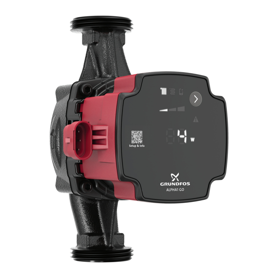
Control functions
Operating panel
LEDs and buttons on the pump display.

| Pos. | Description |
| 1 | Control mode The LED shows the operating mode of the product. |
| 2 | Settings for the selected control mode Use the Selection button to toggle between I, II and III. |
| 3 | QR code The QR code links to information about the pump and how to set it. |
| 4 | If lit, the pump is running in advanced mode. |
| 5 | Selection button Use this button to select control mode and settings. |
| 6 | Warning and alarm A warning is indicated with yellow, and the pump continues operation. An alarm is indicated with red, and the pump stops. |
| 7 | Unit The LED shows the unit used for the number to the left. W = watt. |
| 8 | The LED indicates:
|
Related information
Starting up the product
Venting the product
Overview of LEDs
Control modes
Setting of the product
Overview of LEDs
The LEDs indicate the control mode, setting and operating status.
Factory setting
The pump is factory set to proportional pressure, setting II.
| Active light fields | Description |
 | Advanced mode This mode makes it possible to replicate an UPS pump performance curve. When this function is active, the icon is lit and the control modes on the operating panel are switched off. |
 | Proportional-pressure mode |
 | Constant-pressure mode |
 | Setting I |
 | Setting II |
 | Setting III |
When the symbols for the constant-pressure and proportionalpressure modes are off, the pump is running in constant-curve mode.
Related information
Operating panel
Replacement of a UPS pump
Power saving
In order to lower the energy consumption and heat generation, the operating panel goes into power saving mode after 15 minutes of inactivity. The power saving mode switches off the LEDs in the middle including the dot and the units.
- To reactivate the pump from the power saving mode, press the Selection button.
- If a warning or an alarm is present during power saving mode, only the yellow or red LED will be lit. Press the Selection button to see the error code.
Control modes
ALPHA1 GO can be set to the following control modes:
- constant curve
- proportional pressure
- constant pressure
- replacement mode.
All control modes, including replacement mode, can be set to pump setting I, II, III and can only be set on the operating panel.
Related information Operating panel
Constant curve
In the constant-curve mode, the pump runs at a constant curve, which means that it runs at constant speed or power. The pump performance follows the selected constant curve. This control mode is especially suitable in applications where the characteristics of the heating system are steady, and the emitters require a constant flow. The selection of the constant-curve setting depends on the characteristics of the heating system and the actual required flow and heat demand.

Constant curve
Constant pressure
In the constant-pressure mode, the pump runs at constant pressure, which means the head (pressure difference) is kept constant, regardless of the heat demand (actual number of open zones). The pump performance follows the selected constantpressure curve.
This control mode is especially suitable for underfloor heating and applications where the pump is used to supply a common manifold for multiple zones. The head across each zone will remain constant, independent of how many zones request heat. Thus a constant flow in each zone will be maintained, independent of other zones. The selection of the constant-pressure setting depends on the characteristics of the zones in the heating system and the actual heat demand.

Constant pressure
Proportional pressure
In the proportional-pressure mode, the pump runs at proportional pressure, which means the head (pressure) is reduced at falling heat demand and increased at rising heat demand. The pump performance follows the selected proportional-pressure curve. This control mode is especially suitable for applications where the heat emitters are equipped with a TRV (thermostatic radiator valve) which controls the flow depending on the room temperature. At increased flow, the losses in the distribution system (pipes and fittings) increase, hence the pumps increase the pressure to compensate and vice versa, hereby maintaining an almost constant differential pressure across the thermostatic radiator valve.
The proportional-pressure mode setpoint depends on the heating system's characteristics and the actual heat demand.

Proportional-pressure settings
Replacement of a UPS pump
The product can be used to replace most existing integrated UPS circulator pumps. This means that when you replace an existing integrated pump, the new pump replicates the performance and configuration of the existing pump.
In the Grundfos GO app (via the GO Replace tool) or online via https://grundfos.to/replace, you can check the compatibility of the pump. During the replacement process, Grundfos GO guides you through the replacement process and helps setting up the new circulator pump to match the existing circulator pump.
Related information
Overview of LEDs
Replacing a UPS pump
Replacing a UPS pump
To start the replacement of a UPS pump, follow the steps below:
- Open Grundfos GO.
- The QR code on the front of the ALPHA1 GO circulator pump leads you toGO Replace in Grundfos GO.
- If the app is not installed, the QR code leads you to a download site guiding you to install the app on your device.
- Go to GO Replace.
GO Replace can be found in the Products tab or in the Overview tab after it has been added to Your tools. - To identify the product being replaced, scan the nameplate orenter the 8-digit product number that can be found after "PN:" on the nameplate.
- Follow the instructions in Grundfos GO.
To reset the pump to default settings, follow the steps below:
- Hold theSelection button for 10 seconds until the digits are flashing.
- Set the digits to "0" and wait 10 seconds.
The pump reverts to the factory settings, and you can toggle between the different control modes again.
Related information
Replacement of a UPS pump
Setting of the product
The operating panel can be used for the following:
- Selecting proportional pressure (radiator system), constant pressure (underfloor heating system) or constant curve (speed).
- Selecting pump setting (I, II, III) for the three control modes available on the operating panel.
- Selecting the pump advanced mode to enable the pump to replicate a UPS pump performance.
Related information Operating panel
Service
Electric shock
Death or serious personal injury
- All electrical connections must be carried out by a qualified electrician in accordance with local regulations.
- Switch off the power supply before you start any work on the product. Make sure that the power supply cannot be switched on accidentally.
- A damaged product must be repaired or replaced by Grundfos or a service workshop authorised by Grundfos.
- Connect the pump to earth.
Pressurised system
Minor or moderate personal injury
![]()
- Before disassembling the pump, drain the system or close the isolating valves on both sides of the pump. Slowly loosen the screws and unpressurize the system. The pumped liquid may be scalding hot and under high pressure.
Hot surface
Minor or moderate personal injury
- The pump housing may be hot due to the pumped liquid being scalding hot. Close the isolating valves on both sides of the pump and wait for the pump housing to cool down.

Wear safety shoes.

Wear protective gloves.

Wear safety glasses.
Dismantling the product
Follow the steps below to dismantle the product:
- Switch off the power supply.
- Close the inlet and outlet valves.
- Pull out the power plug.
- Loosen the unions.
- Remove the pump from the system.
Fault finding
Electric shock
Death or serious personal injury
- Switch off the power supply before you start any work on the product. Make sure that the power supply cannot be switched on accidentally.
- A damaged product must be repaired or replaced by Grundfos or a service workshop authorised by Grundfos.
Hot surface
Minor or moderate personal injury
- The pump housing may be hot due to the pumped liquid being scalding hot. Close the isolating valves on both sides of the pump and wait for the pump housing to cool down.
Pressurised system
![]()
Minor or moderate personal injury
- Before disassembling the pump, drain the system or close the isolating valves on both sides of the pump. The pumped liquid may be scalding hot and under high pressure.
Faults indicated on the pump
Faults preventing the pump from operating properly are indicated on the operating panel with the warning and alarm symbol turning either yellow or red.
A warning is indicated when the warning and alarm symbol is turning yellow. The pump is still running, but it does not perform as expected, and action is required in case of insufficient heating or discomfort. The operating panel alternates between showing either the error code or the control mode and setpoint.
An alarm is indicated when the warning and alarm symbol is turning red and the pump stops. In case of an alarm, all modes, speed and unit LEDs are switched off. Action is required.
If an alarm or warning is present, an error code will be displayed in the unit LED display.
| LED | Description |
| | Warning indication |
 | Alarm indication |
Overview of alarm and warning codes
Fault table
| Symbol | Code on operating panel | Fault |
| | E1 | Blocked motor |
| | E2 | Undervoltage |
| E3 | Forced pumping |
| Overvoltage | ||
| Internal fault | ||
| Internal fault | ||
| Internal fault | ||
| | E4 | Dry running |
| | E3 | Impellers forced forward |
Resetting alarms and warnings manually
If an alarm or warning is indicated on the display, and the fault has been corrected, press the Selection button to reset the alarm or warning.
However, if the fault causing the alarm or warning has not been removed, the alarm or warning will appear again.
Noise in the system
| Cause | Remedy |
| The flow is too high. |
|
| There is air in the system. |
|
Code 43 (Forced pumping)
The warning and alarm symbol flashes red, the display shows error code E4 and the pump stops.
| Cause | Remedy |
| Water is missing in the system or the system pressure is too low. |
|
Code 51 (Blocked pump)
The warning and alarm symbol flashes red, the display shows error code E1 and the pump stops.
| Cause | Remedy |
| The pump is blocked. | Only a qualified specialist must perform such work.
|
Code 40 (Undervoltage)
The warning and alarm symbol flashes red, the display shows error code E2 and the pump stops.
| Cause | Remedy |
| The supply voltage to the pump is too low. |
|
Code 4 (Overvoltage)
The warning and alarm symbol flashes red, the display shows error code E3 and the pump stops.
| Cause | Remedy |
| The supply voltage to the pump is too high. |
|
Code 72 (Internal fault)
The warning and alarm symbol flashes red, the display shows error code E3 and the pump stops.
| Cause | Remedy |
| Internal fault. |
|
Code 76 (Internal fault)
The warning and alarm symbol flashes red, the display shows error code E3 and the pump stops.
| Cause | Remedy |
| Internal fault. |
|
Code 85 (Internal fault)
The warning and alarm symbol flashes red, the display shows error code E3 and the pump stops.
| Cause | Remedy |
| Internal fault. |
|
Code 43 (Forced pumping)
The warning and alarm symbol is permanently yellow, the display shows error code E3 and the pump is running.
| Cause | Remedy |
| Other pumps or sources create a flow through the pump. |
|
Technical data
| Supply voltage | 1 × 220-240 V, ± 6%, 50/60 Hz | ||
| Minimum supply voltage | 160 VAC (runs with reduced performance) | ||
| Motor protection | The pump requires no external motor protection. | ||
| Enclosure class | Indoor use only IP44 | ||
| Temperature class | TF110 to EN 60335-2-51 | ||
| Inrush current | < 4 A | ||
| Insulation class | F | ||
| Relative humidity | Max. 95% | ||
| Max. outlet pressure | 1.0 MPa (10 bar) | ||
| Radio frequency radiation exposure | -6 dB CE/EN55014-1, CE/EN55014-2 | ||
| Sound pressure level (LP) | < 25 dB(A) | ||
| Pump housing | Electrocoated cast iron | ||
| Connection type | G 1, G 1 1/4, G 1 1/2, G 2 |
Product size
| Max. flow rate (Q) [m 3 /h] | Max. head (H) [m] | |
| XX-40 | 2.7 | 4.0 |
| XX-60 | 3.5 | 6.0 |
| XX-65 | 3.9 | 6.5 |
| XX-80 | 3.9 | 8.0 |
Power usage (approximate)
| Min. | Max. | |
| XX-40 | 3 W | 27 W |
| XX-60 | 4 W | 45 W |
| XX-65 | 4 W | 60 W |
| XX-80 | 4 W | 60 W |
Liquid temperature
| Max. ambient temperature 55°C | Max. ambient temperature 70°C | |
| XX-40 | 2 to 110°C | 2 to 75°C |
| XX-60 | -10 to +110°C | -10 to +75°C |
| XX-65 | -10 to +110°C | -10 to +75°C |
| XX-80 | -10 to +110°C | -10 to +75°C |
Inlet pressure
| Liquid temperature [°C] | Min. inlet pressure [bar] |
| 75 | 0.05 |
| 95 | 0.5 |
| 110 | 1.08 |
Related information Nameplate
References
Download manual
Here you can download full pdf version of manual, it may contain additional safety instructions, warranty information, FCC rules, etc.
Download GRUNDFOS ALPHA1 GO Manual


