NETGEAR GS308PP Installation Manual
- 1 Package contents
- 2 Register with the NETGEAR Insight app
- 3 Connect the switch
- 4 PoE considerations
- 5 PoE troubleshooting
- 6 Check the PoE status
- 7 Cables and speeds
- 8 Attach the switch to a wall
- 9 Install the switch in a rack
- 10 Change the switch's PoE budget
- 11 Specifications
- 12 Support
- 13 References
- 14 Download manual
- 15 In Other Languages
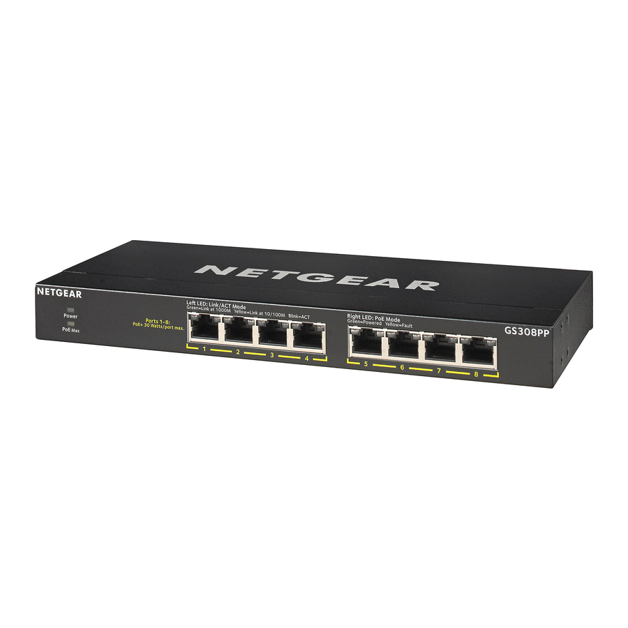
Package contents
- Switch
- Power cord (varies by region)
- Power Adapter (90W)
- Wall installation kit
- Rubber feet
- Mounting ties (for power adapter)
- Rack-mount kit for rack installation
- Installation guide
Register with the NETGEAR Insight app
- Search for NETGEAR Insight and download the latest app.
![]()
![www.apple.com]()
![play.google.com]()
- Set up a NETGEAR account if you do not have one.
- Tap the menu in the upper-left corner.
- Tap REGISTER ANY NETGEAR DEVICE.
- Enter the serial number located on the bottom of the switch, or use the camera on your mobile device to scan the serial number bar code.
- Tap GO.
The switch is registered and added to your account. You can now view the switch in the NETGEAR Insight app.


Note: Because this is an unmanaged switch, you cannot configure or manage it in NETGEAR Insight.
Connect the switch

- Connect network devices to the ports on the switch.
- Connect an RJ-45 port on the switch to a network.
Note: In a small office or home office network, connect the switch to the LAN port of a router that, in turn, is connected to an Internet modem. - Power on the switch.
PoE considerations
The switch prioritizes the PoE+ power that it supplies in ascending port order (from port 1 to port 8). If the aggregate power requirements of all attached power devices (PD) exceed the power budget of the switch, the PD on the highest-numbered port is disabled to make sure that the PDs that are connected to the higher-priority, lower-numbered ports are supported first.
The following tables describe the power adapter models that are compatible with the GS308PP switch and the PoE classes and switch allocations:
Note: The listed total power budget is the maximum power limit for the switch. Many PDs require less than maximum power, so the aggregate power requirements are lower than the maximum, allowing all eight PoE ports to be active simultaneously.
Power adapters and total power budgets for the GS308PP:
| Power adapter model | Power adapter | Total power budget |
| EPS90W | 90W | 83W |
| EPS130W | 130W | 123W |
PoE classes and switch allocations:
| Device class | Standard | Class description | Minimum power allocated to the powered device | Range of power delivered to the powered device | |||||
| 0 | PoE and PoE+ | Default power (full) | 0.44W | 0.44W–12.95W | |||||
| 1 | PoE and PoE+ | Very low power | 4.0W | 0.44W–3.84W | |||||
| 2 | PoE and PoE+ | Low power | 7.0W | 3.84W–6.49W | |||||
| 3 | PoE and PoE+ | Mid power | 15.4W | 6.49W–12.95W | |||||
| 4 | PoE+ only | High power | 30.0W | 12.95W–25.5W |
PoE troubleshooting
Here are some tips for correcting PoE problems that might occur:
- Make sure that the PoE Max LED is off. If the PoE Max LED is solid yellow, disconnect one or more PoE devices to prevent PoE oversubscription. Start by disconnecting the device from the highest-numbered port.
- Make sure that the Ethernet cables are plugged in correctly. For each powered device (PD) that is connected to the switch, the corresponding right port LED on the switch lights solid green. If the right port LED lights solid yellow, a PoE fault occurred and PoE halted because of one of the conditions that are listed in the following table.
| PoE Fault Condition | Possible Solution |
| A PoE-related short circuit occurred on the port. | The problem is most likely with the attached PD. Check the condition of the PD or restart the PD by disconnecting and reconnecting the PD. |
| The PoE power demand of the PD exceeded the maximum level that the switch permits, which is 30.9W. | |
| The PoE current on the port exceeded the classification limit of the PD. | |
| The PoE voltage of the port is outside the range that the switch permits. | Restart the switch to see if the condition resolves itself. |
Check the PoE status

The switch can supply up to 30W PoE+ (IEEE 802.3at) to each port, with a maximum PoE power budget of total 83W with a 90W power adapter and total 123W with a 130W power adapter across all active PoE+ ports.
The PoE Max LED indicates the status of the PoE budget on the switch:
 Solid yellow. Less than 7W of PoE power is available on the switch.
 Blinking yellow. The PoE Max LED was lit solid in the previous two minutes.
 Sufficient (more than 7W of) PoE power is available on the switch (the LED is off).
Cables and speeds
The following table describes the network cables that you can use for the switch connections and the speeds that these cables can support, up to 328 feet (100 meters).
| Speed | Cable Type |
| 100 Mbps | Category 5 (Cat 5) or higher |
| 1 Gbps | Category 5e (Cat 5e) or higher |
Attach the switch to a wall
To attach the switch to a wall, you need the wall-mount screws that are supplied with the switch.
To attach the switch to a wall:
- Locate the two mount holes on the bottom panel of the switch.
- Mark and drill two mounting holes in the wall where you want to mount the switch.
The two mounting holes must be at a precise distance of 4.27 in. (108.4 mm) from each other. - Insert the supplied anchors into the wall and tighten the supplied screws with a No. 2 Phillips screwdriver.
Note: Leave about 0.125 in. (4 mm) of each screw protruding from the wall so that you can insert the screws into the holes on the bottom panel.
Install the switch in a rack
To install the switch in a rack, you need the rack-mount brackets and screws that are supplied with the switch.
To install the switch in a rack:
- Attach the supplied mounting brackets to the side of the switch.
Insert the screws provided in the product package through each bracket and into the bracket mounting holes in the switch. - Tighten the screws with a No. 2 Phillips screwdriver to secure each bracket.
- Align the mounting holes in the brackets with the holes in the rack, and insert two pan-head screws with nylon washers through each bracket and into the rack.
- Tighten the screws with a No. 2 Phillips screwdriver to secure mounting brackets to the rack.
Change the switch's PoE budget
You can move the slider on the back of the switch to increase or decrease the PoE budget. You can increase the PoE budget if you buy a higher wattage power supply. You also can move the slider to a PoE budget that is lower than the power supply wattage. This reduces your switch's power consumption. However, we recommend using the slider setting that matches your power supply.
- Power down the switch and disconnect the power cord.
- Move the slider to the setting that corresponds to the wattage of the new power adapter.
- Connect the power cord and power on the switch.


Specifications
| Specification | Description |
| Network interfaces | 8 Gigabit Ethernet RJ-45 ports that support 1G, 100 M, and 10 M 8 PoE/PoE+ ports |
| Power adapter input | Power cord varies by region. |
| Power adapter output | The switch supports two power adapters:
|
| Max PoE budget | The maximum budget for each power adapter is as follows:
|
| Dimensions (W x D x H) | 9.3 x 4.0 x 1 in. (236 x 102 x 27 mm) |
| Weight | 1.32 lb (0.6 kg) |
| Operating temperature | 32–104°F (0–40°C) |
| Operating humidity | 10%–90% relative humidity, noncondensing |
| Compliance | FCC class A, CB, CE class A, VCCI class A, RCM class A, KC, BSMI |
Support
You can visit https://www.netgear.com/support/ to register your product, get help, access the latest downloads and user manuals, and join our community. We recommend that you use only official NETGEAR support resources.
For regulatory compliance information including the EU Declaration of Conformity, visit https://www.netgear.com/about/regulatory/.
See the regulatory compliance document before connecting the power supply.
Do not use this device outdoors. If you connect cables or devices that are outdoors to this device, see https://kb.netgear.com/000057103 for safety and warranty information.

NETGEAR, Inc.
350 East Plumeria Drive
San Jose, CA 95134, USA
NETGEAR INTERNATIONAL LTD
Floor 1, Building 3
University Technology Centre
Curraheen Road, Cork,
T12EF21, Ireland
© NETGEAR, Inc., NETGEAR and the NETGEAR Logo are trademarks of NETGEAR, Inc. Any non‑NETGEAR trademarks are used for reference purposes only.

References
![www.apple.com]() App Store - Apple
App Store - Apple![play.google.com]() Google Play
Google PlayNETGEAR Support | NETGEAR
Regulatory | NETGEAR
Do I need to use a surge protector with my NETGEAR Business device? | Answer | NETGEAR Support


Download manual
Here you can download full pdf version of manual, it may contain additional safety instructions, warranty information, FCC rules, etc.
Download NETGEAR GS308PP Installation Manual


