Planet IGS-500T, IGS-510TF - Gigabyt Ethernet Switch Manual
Package Contents
In the following section, the term "Industrial Gigabit Ethernet Switch" means the IGS-500T or IGS-510TF.
Open the box of the Industrial Gigabit Ethernet Switch and carefully unpack it. The box should contain the following items:
| Industrial Gigabit Ethernet Switch x 1 | User's Manual x 1 | Wall-mount Kit x 1 |
 |  |  |
| DIN-rail Kit x 1 | RJ45 Dust Caps | SFP Dust Cap x 1 (IGS-510TF only) |
 |  IGS-500T x 5 IGS-510TF x 4 |  |
If any of these are missing or damaged, please contact your dealer immediately; if possible, retain the carton including the original packing material, and use them again to repack the product in case there is a need to return it to us for repair.
Product Specifications
| Model | IGS-500T | IGS-510TF | |
| Hardware Specifications | |||
| Copper Ports | 5 10/100/1000BASE-T RJ45 auto-MDI/MDI-X ports | 4 10/100/1000BASE-T RJ45 auto-MDI/MDI-X ports | |
| SFP Slot | -- | 1 1000BASE-SX/LX/ BX SFP interface compatible with 100BASE-FX SFP | |
| Connector | Removable 6-pin terminal block Pin 1/2 for Power 1; Pin 3/4 for fault alarm; Pin 5/6 for Power 2 | Removable 4-pin terminal block Pin 1/2 for Power 1; Pin 3/4 for Power 2 | |
| Alarm | One relay output for power failure. Alarm relay current carry ability: 1A@DC 24V | -- | |
| Power Requirements | 12~48V DC, redundant power with reverse polarity protection function, 24V AC power support | 9~48V DC, redundant power with reverse polarity protection function, 24V AC power support | |
| Power Consumption (Ethernet Full Loading) | Max. 3.6 watts/12.28BTU | Max. 4.3 watts/14.67BTU | |
| Dimensions (W x D x H) | 30 x 70 x 104 mm | ||
| Weight | 252g | 270g | |
| Enclosure | IP30 metal case | ||
| Installation | DIN-rail kit and wall-mount kit | ||
| ESD Protection | 6KV | ||
| EFT Protection | 6KV | ||
| Switch Specifications | |||
| Switch Architecture | Store-and-Forward | ||
| Switch Fabric | 10Gbps | ||
| Throughput (packet per second) | 7.4Mpps@64bytes | ||
| Address Table | 4K entries | ||
| Buffer Memory | 1M bits on-chip buffer memory | ||
| Jumbo Frame | 9Kbytes | ||
| Flow Control | Back pressure for half duplex IEEE 802.3x pause frame for full duplex | ||
| Standards Conformance | |||
| Regulatory Compliance | FCC Part 15 Class A, CE | ||
| Stability Testing | IEC 60068-2-32 (free fall) IEC 60068-2-27 (shock) IEC 60068-2-6 (vibration) | ||
| Standards Compliance | IEEE 802.3 Ethernet IEEE 802.3u Fast Ethernet IEEE 802.3ab Gigabit Ethernet IEEE 802.3az Gigabit SX/LX (IGS-510TF only) IEEE 802.3x Full-Duplex Flow Control IEEE 802.3az Energy Efficient Ethernet (EEE) IEEE 802.1p Class of Service | ||
| Environment | |||
| Temperature | Operating: -40~75 degrees C Storage: -40~75 degrees C | ||
| Humidity | Operating: 5~90% (non-condensing) Storage: 5~90% (non-condensing) | ||
Hardware Introduction
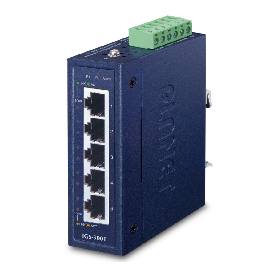
Switch Front Panel
The front Panels of the Industrial Gigabit Ethernet Switches consist of Ethernet interfaces and LED indicators.
- Front View


LED Definition
| LED | Color | Function |
| P1 | Green | Lights to indicate power input 1 has power. |
| P2 | Green | Lights to indicate power input 2 has power. |
| Fault | Red | Lights to indicate that power 1 or power 2 has failed. (For IGS-500T only) |
| 1000 LNK/ACT | Green | Lights to indicate the port is running at 1000Mbps speed and successfully established. |
| Blinks to indicate that the Switch is actively sending or receiving data over that port. | ||
| 100 LNK/ACT | Amber | Lights to indicate the port is running at 10/100Mbps speed and successfully established. |
| Blinks to indicate that the Switch is actively sending or receiving data over that port. |
Switch Upper Panel
The upper panels of the Industrial Gigabit Ethernet Switches consist of one terminal block connector within two power input.


Wiring the Power Inputs
The terminal block connector on the top panel of Industrial Gigabit Ethernet Switch is used for two DC redundant power inputs. Please follow the steps below to insert the power wire.

When performing any of the procedures like inserting the wires or tightening the wire-clamp screws, make sure the power is OFF to prevent from getting an electric shock.
[IGS-500T]
- Insert positive and negative DC power wires into contacts 1 and 2 for POWER 1, or contacts 5 and 6 for POWER 2.


- Tighten the wire-clamp screws for preventing the wires from loosening.


[IGS-510TF]
- Insert positive and negative DC power wires into contacts 1 and 2 for POWER 1, or contacts 3 and 4 for POWER 2.

- Tighten the wire-clamp screws for preventing the wires from loosening.


The wire gauge for the terminal block should be in the range between 12 and 24 AWG.
- The power input range is 12V ~ 48V DC for IGS- 500T, 9 ~ 48V DC for IGS-510TF and supports 24V AC.
- Use one power input when using 24V AC.
Wiring the Fault Alarm Contact (IGS-500T Only)
The fault alarm contacts are in the middle of the terminal block connector as the picture shows below. Inserting the wires, the Industrial Gigabit Ethernet Switch will detect the fault status of the power failure and then forms an open circuit. The following illustration shows an application example for wiring the fault alarm contacts.

(The Fault Alarm Contacts are energized (CLOSE) for normal operation and will OPEN when failure occurs)
- The wire gauge for the terminal block should be in the range between 12 and 24 AWG.
- Alarm relay circuit accepts up to 24V DC, 1A.
Grounding the Device
Users MUST complete grounding wired with the device; otherwise, a sudden lightning could cause fatal damage to the device.

EMD (Lightning) DAMAGE IS NOT CONVERED UNDER WARRANTY.
Installation
This section guides you to installing the Industrial Gigabit Ethernet Switch on the DIN rail and wall. Please read this chapter completely before continuing.
This following pictures show how to install the device. However, the device in the picture is not IGS-500T or IGS-510TF.
DIN-rail Mounting Installation

Wall-mount Plate Mounting

Side Wall-mount Plate Mounting (IGS-510TF Only)


You must use the screws supplied with the wallmounting brackets. Damage caused to the parts by using incorrect screws would invalidate your warranty.
Three-View Diagram
The three-view diagram of the Industrial Gigabit Ethernet Switch consists of multiple auto-sensing 10/100/1000BASE-T RJ45 ports and one removable terminal block. The LED indicators are also located on the front panel.
- IGS-500T


- IGS-510TF


Customer Support
You can browse our online FAQ resource on PLANET web site first to check if it could solve your issue. If you need more support information, please contact PLANET switch support team.
PLANET online FAQs: http://www.planet.com.tw/en/support/faq
Switch support team mail address:
support@planet.com.tw
Copyright © PLANET Technology Corp. 2019.
Contents are subject to revision without prior notice.
PLANET is a registered trademark of PLANET Technology Corp.
All other trademarks belong to their respective owners.

References
Download manual
Here you can download full pdf version of manual, it may contain additional safety instructions, warranty information, FCC rules, etc.
Download Planet IGS-500T, IGS-510TF - Gigabyt Ethernet Switch Manual


