Maytag LEGACY, LEGACY II, DIMENSION, DIRT FINDER Manual
Legacy/Legacy II Overview

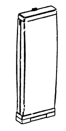
Legacy - Hard Bag Overview

DImension Overview

Dirt Finder Overview

General
These uprights are lightweight upright vacuums that feature high performance computer design motors, double edge cleaning, quick release cord wraps and top conversion cleaning tools.
All models have automatic height adjustment in that the nozzle is free to float up and down on the carpet. These models additionally have front wheel height control to limit the minimum nozzle height which allows the user to select the proper setting for optimum operation on various types of carpets.
The Legacy and Legacy II models use Type "A" top-fill disposable bags.
The Dimension/Dirt Finder uses Type "Z" top-fill disposable bags.
Microfiltration bags are available for both models.
Operation
These cleaners operate on a Dirty Air System principle, i.e., dirty air passes through the motor area (fan) before reaching the bag.
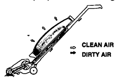
As illustrated, air and dirt are sucked through the molded agitator housing and directed into the motor area. The fan then propels the air and dirt up the handle passage and into the throw-away bag.
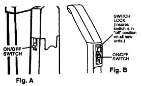
The Legacy units are controlled by an on/off switch located on the side of the unit. (Fig. A)
The Legacy II, Dimension and Dirt Finder units are controlled by an on/off switch located in the front of the upper handle.(Fig. B)
The carpet height adjustment lever has four settings for carpet cleaning and one for the top tool conversion.
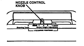
It is important that the unit be in the proper setting (carpet - for floor cleaning, and cleaning tools when using the hose and tools). This will ensure optimum performance.
The cleaning tool hose attaches to the unit through the tool door located on the top of the hood. The air is directed to the hose by adjusting the nozzle control knob to the cleaning tool position.
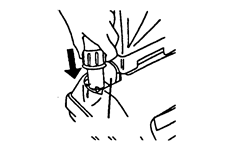
The valve gate operates in conjunction with the height adjustment lever. When the lever is in any one of the four carpet settings the valve gate is open. The cam is not contacting the valve gate.

As the lever is moved to the cleaning tools position the cam locks on to the gate and slides it to shut off suction to the agitator cavity.

 Note: These illustrations are shown without the bottom plate or wheel assembly in place.
Dirt Finder feature:
The embedded Dirt Finder system is powered by a regular 9V alkaline battery. The battery is located in a holder inside the bag compartment.
The circuitry is energized when the cleaner on/off switch is turned to the on position. A separate switch mounted in the bag housing is actuated by a raised rib on the upper switch rod.
A microphone, located near dirt duct, senses debris that strikes the tube and signals the circuit board which controls the lights.
The green light signifies clean and the red dirty.
It is important to note that when you turn on the unit the red light will come on. After a few seconds the red light will go off and the green light will come on. This function lets you know the Dirt Finder feature is ready. If this lighting pattern does not occur check the troubleshooting portion of this instruction.
Disassembly
Models with a bag door skip to section B.
- Outer bag (Legacy and Legacy II Models)
![]()
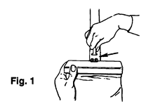
- Release jacket support upper from bag strap (Fig. 1).
![]()
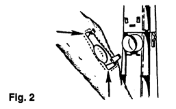
- Release outer bag retention clips (Legacy - 2 upper, 2 lower; Legacy II - 2 upper, the 2 lower tabs are there but are not fastened)... grasp bag attachment collar support area and pull out. (Fig. 2)
![]()
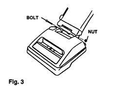
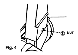
- Remove handle bolt and nut (Fig. 3 & 4).
![]()
![]()
- Remove outer bag.
![information]() Note: Re-assemble in reverse order.
Note: Re-assemble in reverse order.
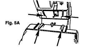
The retention/guide ribs on the jacket support lower must mate with the retention/guide ribs on the lower handle. (Fig. 5A).
Note: Units without bag door skip to Section D.
- Bag housing (Legacy II and Dimension) Bag housing/Dirt Finder circuitry (Dirt Finder)
- Remove bag door.
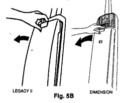
- Pull bag door latch forward and remove door from cleaner (Fig. 5B).
![]()
- Pull bag door latch forward and remove door from cleaner (Fig. 5B).
- Remove throw-away bag.
- Remove bag housing.
- Release two tabs on inside of bag housing located above dirt tube (Fig. 5C)
![]()
- Release two tabs on inside of bag housing located above dirt tube (Fig. 5C)
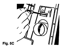
Note: On Dimension/Dirt Finder models, the tool door and holder must be removed to access the tabs.
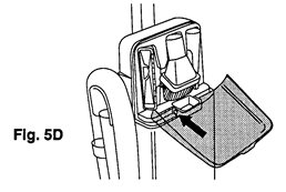
To remove tool door/tool holder.
- Unsnap hinges at base of door (where applicable to remove (Fig. 5D).
![]()
- Remove tool holder mounting screw (located in screw cavity under the dusting brush).
- Pry outward on both sides of the tool holder to release tabs and pivot holder out of position (Fig. 5E).
![]()
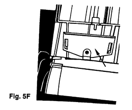
- Lift bag housing out of bag housing bracket located on lower handle. (Fig. 5F)
![]()
- Lift bag housing out of bag housing bracket located on lower handle. (Fig. 5F)

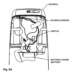
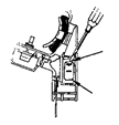
- Dirt Finder circuitry
At this point you can access the dirt finder circuitry. This circuitry is housed in the bag housing. Fig. 5G is a cutaway view that illustrates positioning of the components and switch from the back of the bag housing.
![]()
![]()
- Switch
- Disconnect leads and snap switch out of bag housing.
- Circuit Board
- Remove housing screws.
- Snap circuit board out of housing and disconnect leads.
Note: The discharge of static electricity to a circuit board can damage the component. When removing the circuit board from the special anti-static bag, the following precautions should be taken.
- Avoid being statically charged when handling board. Serviceman should ground himself if possible.
- Circuit board should be handled by outside edge or metal heat sink only.
- DON'T touch the metal traces (circuits) on bottom of circuit board.
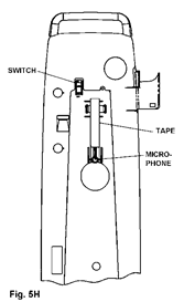
- Microphone
The microphone is housed in the bag housing above the opening for the dirt duct (Fig 5H).
To remove:
- Grasp microphone leads near the base of the microphone and slowly pull the mic out of the seat.
- Disconnect leads at board (Fig 5I)
![]()
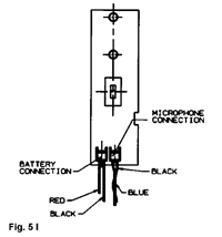
Note: It is important upon reassembly of the microphone to firmly push the microphone into the seat in bag housing. Also, replace the electrical tape and position as illustrated in Fig. 5H. This will insure optimum performance of the microphone.
- Bag housing bracket
- Remove handle bolt and nut.
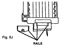
- Remove bracket by sliding it off of the tapered rails located on the lower handle. (Fig. 5J).
![]()
- Jacket support cap (Legacy, Legacy II models with air freshener dispenser)
- Remove air freshener dispenser.
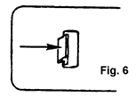
- Locate and release the two retention tabs for the cap on the inside of the jacket. (Fig. 6).
![]()
- Remove cap.
- Jacket support - upper (Legacy, Legacy II models without air freshener dispenser).
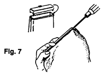
- Release 6 retention tabs on inside of jacket support upper and separate outer bag collar from jacket support. (Fig. 7).
![]()
- Jacket Support - Lower
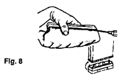
- Release 6 retention tabs on inside of jacket support lower and separate outer bag collar from jacket support. (Fig. 8)
![]()
- Tool rack (Legacy, Legacy II models)
- Remove tools.
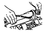
- Remove hose.
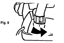
- Rotate hose in opposite direction of indicator arrow and remove hose. (Fig. 9)
![]()
- Rotate hose in opposite direction of indicator arrow and remove hose. (Fig. 9)
- Remove bag housing (where applicable)
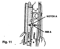
- Remove retaining screw located on the back of the handle and remove rack. (Fig. 10).
![]()
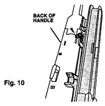
For proper alignment of the tool rack during re-assembly, hook Notch A of rack on rib A of the handle. (Fig. 11).
- Attachment cord - handle upper/lower - switch control rod
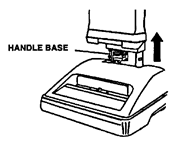
With jacket or bag housing, tool rack and handle nut and bolt removed, the handle can be disassembled by grasping and pulling upward off of motor assembly.

Be careful not to set handle assembly down on exposed switch rod at handle base. This could damage rod.
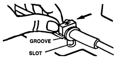
- Remove attachment cord.
- Slide cord protector and connector out of handle upon re-assembly, be sure to align the arrow on the cord protector and press groove in cord protector into slot in handle.
![]()
Press the cord into place on the three notches indicated below.
![]()
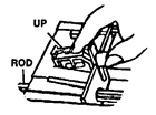
Position the connector in the handle with the "UP" side visible.
![]()
- Slide cord protector and connector out of handle upon re-assembly, be sure to align the arrow on the cord protector and press groove in cord protector into slot in handle.
- Separate handle.
- Separate by grasping both halves and pulling apart. (Fig. 12)
![]()
- Separate by grasping both halves and pulling apart. (Fig. 12)
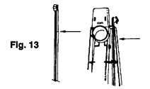
- Remove switch control rod from the lower handle.
The lower rib of the switch control rod is tapered as shown in Fig. 13. This protrusion must be raised to clear the support rib in the lower handle (Fig. 13) in order to facilitate removal.
![]()


NOTE: Early model Legacy II lower handle assembly includes an integral muffler system. This system consists of a muffler louver, muffler foam and a muffler cover. All of these items are permanently attached to the lower handle so if a problem related to the system occurs the complete lower handle assembly must be replaced. This handle with muffler is no longer available in service.
- Upper Handle Assembly -
The upper handle's are stocked as assemblies only.
The serviceable components are the bag strap and spring on models without the hard bags.
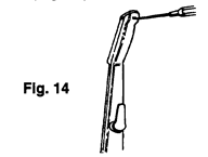
To service bag strap.
- Remove the handle grip from the upper handle by releasing the handle cap retention tab. (Fig. 14)
![]()
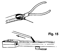
The bag strap spring is retained to the upper handle and can now be removed in conjunction with the bag strap (Fig. 15)
![]()
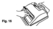
- Hood
- Remove height adjustment indicator knob (friction fit). (Fig. 16)
![]()
- Turn cleaner over and remove the 4 hood retention tabs. (Fig. 17).
![]()
- Remove hood.
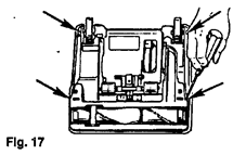
Note: The furniture guard is molded onto the hood and is not replaceable.
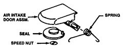
Air intake door assembly.
Remove door assembly by unsnapping it from the locator bosses on the inside of the hood.
All the components of the door assembly listed are replaceable.
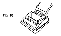
Headlight lens/panel
The headlight lens and/or panels are removable by releasing the retention tabs as illustrated. (Fig. 18)
- Headlight
- Remove hood.
- Remove bulb by pulling straight out of socket; push new bulb into socket until it locks in place.
![]()
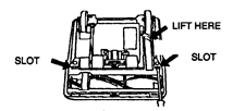
- Bottom plate
- Place screwdriver in RH slot and remove bottom plate.
![]()
- Agitator - belt
- Remove bottom plate.
- Remove hood.
- Remove belt from motor shaft.
- Slide agitator and belt out of housing.
![]()
Note: When re-assembling belt, follow the diagram on the main body for proper orientation.
For instructions concerning the agitator see agitator section.
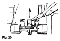
- Front wheel support/wheels/lever
- Remove bottom plate.
- Release the cam actuator spring from the front wheel support retaining boss and remove by pulling it out of the main body retention pocket. (Fig. 20)
![]()
- Pivot assembly upward and remove from unit.
On Legacy units, you will encounter one of the two wheel arrangements illustrated below. (Fig. 21,22)
Early Design
Models produced prior to 4/8/91 lever positioned on outer edge of the support.
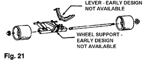
Latest Design
Models produced after 4/8/91 lever positioned in the center of the support.

The latest lever will be available in service for use on both style supports and is a drop-in replacement..
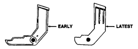
The early design wheel supports are no longer available in service. Updating the unit from the early style support to the latest will require replacement of the main body.
Wheels
Remove wheels from support by prying wheel retainer from shaft and sliding shaft out of support.
Note: Replace the wheel retainers once they are removed from the shaft.
Lever Remove lever by unsnapping it out of the support.

- Valve gate
- Remove bottom plate.
- Slide valve gate out of housing (Fig. 23).
![]()
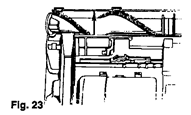
Note: On the late model units, the main body has been revised so the valve gate "snaps" into position and is retained in the main body.
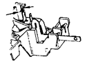
- Nozzle height adjustment cam/cam actuator
- Remove bottom plate.
- Remove valve gate.
- Remove front wheel support.
- Remove hood.
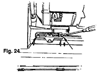
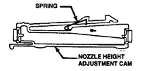
- Release the 2 nozzle height adjustment cam retention tabs (Fig. 24)
- Separate nozzle height adjustment cam and cam actuator.
![]()
The spring on the cam is replaceable.
- Rear wheels
- Release the rear wheel shaft from the main body retention slots. (Fig. 25)
![]()
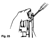
Note: The main body must be flexed on one side or the other of the rear wheels while pulling upward on the rear wheel shaft and then on the other side of the rear wheel to facilitate removal.
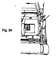
- Handle release lever
- Remove hood.
- Lower handle to its lowest position.
- Release the handle lever shaft protrusion fromthe main body retention slots. (Fig. 26).
![]()
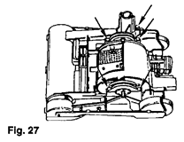
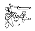
- Motor assembly
- Remove handle.
- Remove hood.
- Release belt from the motor shaft.
- Remover motor retainer right half and left half.
![]()
- Lift motor off the main body. Check for the seal at the inlet to the fan chamber. This seal is friction fit and slides out of the housing.
Motor (See the exploded view)
Motor service
Serviceable components are listed on the above schematic. Failure of any component not listed requires replacement of the entire motor.
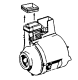
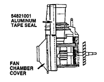
Fan
- Remove light bulb by pulling straight out of the socket.
- Remove four screws which retain the fan chamber to the motor end cap assembly.
- Remove motor end cap assembly by sliding it off the fan chamber and motor housing assembly.
- Remove the molded duct seal by sliding it off the housings.
![]()
- Lift off fan chamber and remove fan (LH thread)
At this point, you have broken a latex paint seal between the motor housing and fan chamber cover. It is important that aluminum tape be installed in its place as shown below.
Motor brush holder assembly
(Replaced as an assembly which includes motor brush and holder)
- Remove four screws which retain fan chamber to motor end cap assembly.
- Slide fan chamber and motor housing assembly out of motor end cap assembly.
- Grasp motor brush holder assemblies with pliers and slide then outward to release the terminal connection.
Upon reassembly of new motor brush holder assemblies, position holders and slide them into place insuring the field terminal connection and continue to insert until they stop.
Do not grasp outside of brush holder with pliers as it could damage the holder and cause the carbon brush to stick.

On/off switch
- Remove fan.
- Remove brush holders.
- Remove armature.
- Remove field assembly
- Remove switch/attachment cord terminal blade.

![]()
- Remove field winding lead from switch terminal by uncrimping connection.
![]()
- Remove switch by releasing switch pressure tabs and snapping switch out of holder.
![]()

Note: When installing a new switch, the field winding lead must be securely crimped to the proper switch terminal.
Troubleshooting check list
Legacy/Legacy II/Dimension/Dirt Finder
The following is a guide to aid in determining the origin of a problem for which these models could conceivably be brought in for service.
| PROBLEM | POSSIBLE CAUSE | POSSIBLE SOLUTION |
|
|
|
|
|
|
|
|
|
|
|
|
|
|
|
|
|
|
This section addresses problems associated with the Dirt Finder feature in the Dirt Finder unit.
| PROBLEM | POSSIBLE CAUSE | POSSIBLE SOLUTION |
|
|
|
| Note: Normal lighting pattern is discussed in the basic operation section of this instruction | ||
|
|
|
| Note: To check lighting pattern, unplug unit, turn cleaner switch to on (green light will illuminate). Tap inside the opening of the dirt duct with a screwdriver. The light should change from green to red. If the light does not change, check the following. | ||
|
| |
Download manual
Here you can download full pdf version of manual, it may contain additional safety instructions, warranty information, FCC rules, etc.
Download Maytag LEGACY, LEGACY II, DIMENSION, DIRT FINDER Manual


