Thetford C502-C, C502-X, C503-L, C500 Series Manual
Introduction
General
This is the installation manual for the Thetford C502-C, C502-X and C503-L. The manual is meant for qualified installers who will install the toilet system in a caravan or camper. Read the information and instructions carefully and follow them strictly to install the toilet system safely and correctly. Also read the warnings in the user manual before testing the toilet system after installation. This document is version 90100/0924-V03 of the installation manual. Our policy is one of continuous development and improvement. Specifications and illustrations may change subsequent to publication. Please visit www.thetford.com for the most recent version.
Symbols
The following symbols may be used in this manual:

Risk of serious injury and/or damage.

Risk of moderate injury and/or damage.
 Attention. Important information.
 Note. Additional information.
 Video. Additional instruction video available.
Serviceability
The installer of Thetford products is responsible for correct installation according to the Thetford installation instructions to ensure the functionality and serviceability of the product. In terms of serviceability, this means that a dealer or authorised Thetford service partner must be able to remove and re-install the Thetford product within the time that is allowed according to the Thetford time-list, using standard tools and equipment. This is to claim any warranty during the warranty period after the purchase date. In case of any queries on this subject, a Thetford local service representative can be contacted for additional support related to the installation of the product.
Designation codes, drawings and models
Each product has a specific identification code, the designation code. The designation code can be found on the data badge. See Service & questions for the location of the data badge. The different positions of the code stand for different variations of the toilet. In these instructions, the designation will be used as reference.
Table 1: Designation example C50 2 X – N 062 R 21 X 01
| C50 | 2 | X | – N | 062 | R | 75 | X | 01 |
| Type of water supply | Version | Colour | Slide out direction wasteholding tank | Type of tunnel | Type of level indication |
Table 2: Available drawings and models
| Designation | Description | 2D drawing | 3D file |
| C50xx – x xxx L 75 x xx | C500 left - straight cosmetic cover - tunnel 103mm | LE973 | LE748 |
| C50x x – x xxx R 75 x xx | C500 right - straight cosmetic cover - tunnel 103mm | LE973 | LE749 |
| C50x x – x xxx L 74 x xx | C500 left - curved cosmetic cover - tunnel 103mm | LE746 | LE750 |
| C50x x – x xxx R 74 x xx | C500 right - curved cosmetic cover - tunnel 103mm | LE746 | LE751 |
| C50xx – x xxx L 76 x xx | C500 left - curved cosmetic cover - tunnel 145.5mm | LE832 | LE877 |
| C50x x – x xxx R 76 x xx | C500 right - curved cosmetic cover - tunnel 145.5mm | LE832 | LE878 |
| C50x x – x xxx L 77 x xx | C500 left - straight cosmetic cover - tunnel slide out 103mm | LE831 | LE748 |
| C50x x – x xxx R 77 x xx | C500 right - straight cosmetic cover - tunnel slide out 103mm | LE831 | LE749 |
| N/A | Waste-holding tank | LE753 | LE752 |
The 2D drawings consist of product dimensions and screw positions.
The 2D drawings are available upon request, 3D files are only available for the professional builder.
Technical specifications
Table 3: Electrical specifications
| Item | Description/specification |
| Operating voltage | 10–15V (power supply must be able to deliver 3A at rated voltage)The voltage must be between 11.4V and 13.8V to be able to achieve full bowl coverage flush. |
| Connection | C502-C / C502-X: 2 pole connector plug C503-L: 2 pole connector plug + 2x 1 pole connector plug (potential free contacts) |
| Position wiring in tab housing |  |
| 2 pole connector on toilet | TYCO/AMP 180908 |
| 2 pole connector counter part | TYCO/AMP 180907 |
| 1 pole connector on toilet | TYCO/AMP 180916 |
| 1 pole connector counter part | TYCO/AMP 925324 |
| Thickness | 0.5mm 2 |
Table 4: Wiring diagram C502-C

- Pump
- Controller
- Main PCB
- Black
- Red
Table 5: Wiring diagram C502-X

- Pump
- Water sensor
- Controller
- Main PCB
- Black
- Red
Table 6: Wiring diagram C503-L

- Valve
- Controller
- Main PCB
- Relais
- Purple COM
- Grey NO
- Black
- Red
Table 7: Capacities and weight
| C502-C | C502-X | C503-L | |
| Empty weight | 9.5kg | 9.5kg | 9.6kg |
| Capacity waste-holding tank | 19.7L | 19.7L | 19.7L |
| Level indication waste-holding tank | 1 level | 3 levels | 3 levels |
| Capacity flush-water tank | 16.5L | 16.5L | - |
| Level indication flush-water tank | - | 3 levels | - |
Table 8: C503-L water supply
| Diameter | Inside: 10mm Outside: 16mm |
| Length and position | 400mm from the side of the toilet |
| Required pressure remote pump at the toilet inlet | Min. 0.4bar at 5.2L/min Max. 0.8bar at 8L/min |
| Maximum allowable pressure on hose | Europe: 4bar AUS/China/US: 8bar |
Meet the required pressure for the remote pump at the toilet inlet to ensure correct flush. If the pressure is too high, install a flow restrictor.
Packaging
Table 9: Packaging
| Type of packaging | Pallet packaging |
| Amount of toilets on a pallet | 6 (2x3) |
| Maximum stack height | 3 pallets high |
| Pallet size | 1200 x 800mm |

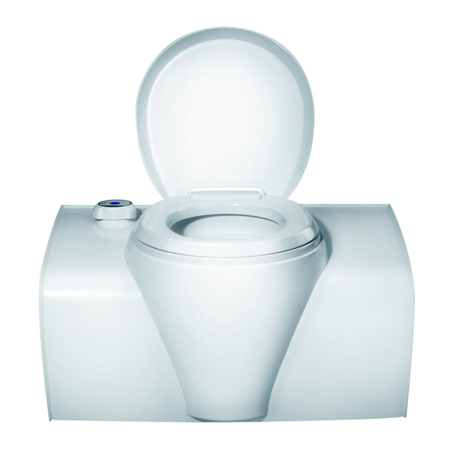
Only carry the toilet at the grips on the bench upper (1). Do not carry the toilet at the tunnel (2) or the cosmetic cover (3).
Leave green tape and blue foil on during handling and assembly. Only remove after installation.
Before installation
Content of the box
For the single-piece packaged appliance, check the content:
- One toilet appliance
- Installation manual (this manual)
If something is missing, please contact your dealer.
Bathroom dimensions
The dimensions below are applicable to toilets used with a service door. When using a flush door, add 2.5mm to the dimensions indicated with a *.


- The other dimensions:


- The floor-wall angle:


- The distance to the outside wall:


- The available space underneath the toilet:


(*) Depending on the model. Please refer to the dimensions of the various models, earlier in this chapter.
Prepare bathroom
See Designation codes, drawings and models for drawings of the cut-out dimensions.
The wall thickness needs to be between 23mm and 39mm for a service door or between 28mm and 40mm for a flush door. Contact Thetford if the vehicle wall thickness is outside this range.
- Create a cut-out in the back wall for the flange on the tunnel.


- Create the wall cut-outs for the service door or flush door.
- Install the service door or flush door.
- For further instructions, see the installation instructions of the door.
When using a flush door, an extra cut-out must be created in the back wall for the flange on the frame inner.


- Mount the wall bracket.
![warning]() Up to 30% of the vertical force applied to the toilet can be transferred as a horizontal load to the wall bracket connection.
Up to 30% of the vertical force applied to the toilet can be transferred as a horizontal load to the wall bracket connection.
![information]() The wall bracket is sold separately.
The wall bracket is sold separately.


- Install a shower tray, if applicable.

- Connect the toilet to the wall bracket.
![warning]() Leave green tape and blue foil on during handling and assembly. Only remove after installation.
Leave green tape and blue foil on during handling and assembly. Only remove after installation.


- Only for C50xx x xxx x 76 x xx: Fold out the tunnel and secure it with 4 screws.


- If desired, mount the toilet to the floor with four screws.
![information]() Screws are supplied by Thetford. If these are not used, use stainless steel screws.
Screws are supplied by Thetford. If these are not used, use stainless steel screws.
![information]() Required torque: 1.2 ± 0.3Nm for a Plywood floor.
Required torque: 1.2 ± 0.3Nm for a Plywood floor.
![information]() Torque may differ if the floor is made from a different material.
Torque may differ if the floor is made from a different material.


Ensure the wall seal is positioned correctly.

Installation
Read the applicable instructions in chapter Safety first.
Make sure the cabinet is properly prepared, see Before installation for this.
- Prepare the bathroom for the appliance.
- Place the appliance over the support bracket.
![warning]() Make sure the appliance is located correctly in the designated space and the wall seal is positioned correctly.
Make sure the appliance is located correctly in the designated space and the wall seal is positioned correctly. - Ensure all fasteners are tightened with the correct amount of torque.
- C503-L only: connect the water hose.

- Connect the electrical supply.

![]()


- Remove the green tape and blue foil.
After installation
Read the applicable instructions in chapter Safety first.
Visual and functional checks
Check if:
- All packaging materials have been removed.
- The wall seal is positioned correctly.
- The toilet flushes correctly.
- The level indication works.
- All piping and connections do not leak.
- It is possible to drain the water system completely to prevent frost damage.
- The waste-holding tank can be removed and placed back.
- The doors open and close properly.
- The doors are waterproof after installation.
- Electrical cables are not pinched or damaged.
- Electrical cables are not routed close to heat sources (such as hob, oven or heater) and ignition sources.
- Electrical connectors are seated correctly.
Service & questions
Read the applicable instructions in chapter Safety first.
Service
Before starting any service work, disconnect the appliance from the electrical supply.
All servicing must be carried out by an approved competent person.
Questions
If you have questions about your product, parts, accessories or authorised services visit www.thetford.com.
If you contact an authorised local Service Centre in your country, provide the details of the model and serial number plus the date of purchase. The data badge can be found on the base of the toilet.


Safety
General
Risk of serious injury through burning, explosion, clamping, electrocution, suffocation and poisoning or damage to the product.
- Do not modify this appliance, unless the modification is authorised and carried out by the manufacturer or their agent.
- If the appliance is not installed in accordance with national and European law, regulations, rules and standards, this will void the warranty and may lead to criminal prosecution.
- Wear the correct Personal Protective Equipment during the installation. Also follow the applicable safety regulations.
- Only qualified and certified professionals are allowed to install the appliance and connect its electrical components.
Installation
Risk of serious injury through burning, explosion, clamping, electrocution, suffocation and poisoning or damage to the product.
- Do not install this toilet in a fixed indoor cabin or other dwelling applications. This toilet is made for use in RV and towable applications.
- To avoid a hazard due to instability of the appliance, it must be fixed in accordance with the instructions.
- The toilet must be installed in a way that allows easy access for maintenance and repairs.
- Do not install the toilet directly on carpet. Put the toilet on a metal or wood panel that extends the full width and depth of the toilet.
- Do not drill, cut or use excessive force on the toilet walls, except for screwing predefined positions. This may damage the appliance.
- When installing the appliance, ensure cables are not trapped or damaged.
- Install the electrical connections in such a way that wires can't come into contact with hot or sharp parts.
- Route the cables away from the appliance and other heat sources.
- Do not allow cables to hang loose into the compartment.
- Never reposition or change the electronic components unless stated otherwise in this manual.
- Use only genuine and approved parts and materials.
Electrical
Risk of serious injury through burning, explosion, clamping, electrocution, suffocation and poisoning or damage to the product.
- Ensure the installation and materials used are in accordance with the latest legislation and regulations on electrical installations in the country of use.
- The electrical connections have to comply with EN60335.
- Observe polarity to prevent damage to the appliance and/or damage to other apliances connected to the 12V DC circuit: - +12V DC or positive wire is coloured red. - -12V DC or negative or ground wire, is coloured black or white.
- Do not locate multiple portable socket-outlets or portable power supplies at the rear of the appliance.
Commissioning
Do not switch on the appliance without first carrying out the visual and functional checks.
References
Download manual
Here you can download full pdf version of manual, it may contain additional safety instructions, warranty information, FCC rules, etc.
Download Thetford C502-C, C502-X, C503-L, C500 Series Manual


