Manfrotto MKBFR1A4B-BH, MKBFR1A4R-BH, MKBFR1A4D-BH - Tripod Manual
- 1 SET UP
- 2 LEG ANGLE ADJUSTMENT
- 3 CENTRE COLUMN HEIGHT ADJUSTMENT
- 4 FITTING THE QUICK RELEASE PLATE TO THE CAMERA
- 5 MOUNTING THE CAMERA ON THE HEAD
- 6 REMOVING THE CAMERA FROM THE HEAD
- 7 USE
- 8 FOLD THE TRIPOD WITH CAMERA PLATE REMOVED
- 9 LEG LOCK TENSION ADJUSTMENT
- 10 MAINTENANCE
- 11 Download manual
- 12 In Other Languages
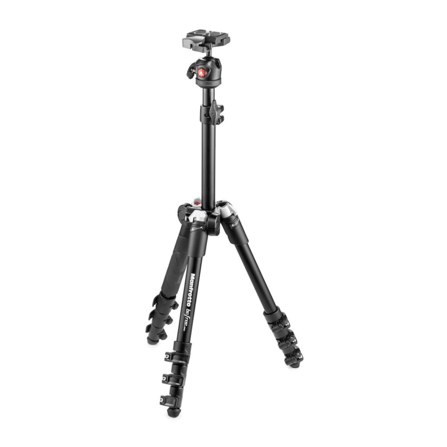
SET UP

Unfold the legs as shown in fig. 1 Open the 3 tripod legs.
To adjust the height of the tripod, each leg has telescopic extensions that can be released by rotating lever "A" on the locking collar "B".
LEG ANGLE ADJUSTMENT

Each leg can be set independently at either of the two angles of spread.
To change a leg angle, close the leg slightly by folding it towards the centre column (fig. 2), rotate the angle selector "W" to the position desired (indicated by the symbols) then open the leg fully again.
CENTRE COLUMN HEIGHT ADJUSTMENT

To release the centre column "C", unlock knob "D". Adjust the height of the column as required, then tighten knob "D" to lock the column in position.
FITTING THE QUICK RELEASE PLATE TO THE CAMERA

Fix plate "G" to the base of the camera by tightening camera screw "M" in the camera's threaded tripod hole using the ring "Q" WITHOUT APPLYING FORCE.
Before fully locking, align the plate "G" with the camera lens.
Please ensure you have securely fastened plate "G" to the camera before use.
Once fastened, push ring "Q" (fig. 4) down so that it lies flat against the plate "G".
MOUNTING THE CAMERA ON THE HEAD


To mount the camera on the head (fig. 5), open lever "H" and at the same time push safety catch "X" down, hold them in the open position whilst attaching the camera by slotting camera plate "G" into the top of the head as shown in fig. 5. Release lever "H" and safety catch "X".
 Make sure that the camera is locked securely to the head by pushing lever "H" against plate "G" (fig. 6) and checking that the camera doesn't move in the head.
REMOVING THE CAMERA FROM THE HEAD

To remove the camera from the head (fig. 7), open lever "H" and at the same time push safety catch "X" down. Hold them in the open position whilst removing the camera as shown in fig. 7.
USE

Knob "P" is the head movement lock. Whenever operating knob "P", please make sure you are holding on to the camera securely with one hand.
To reposition the camera, unlock lever "P" by rotating anticlockwise until the ball "N" can move freely.
Once the desired position is achieved, block the ball "N" by turning lever "P" clockwise until locked.
FOLD THE TRIPOD WITH CAMERA PLATE REMOVED

Unlock knob "P", unlock knob "D", lower the column "C" (not completely) and then block it again with the knob "D". Close your legs slightly toward the center column "C", turn the angle "W" of each leg on the "closed" position (marked), then fold completely the three legs up. The legs of the tripod must fit on the head.
LEG LOCK TENSION ADJUSTMENT

If the telescopic leg extensions slip even after having tightened the locking lever "A", or if locking levers "A" are too stiff for you to use, the locking tension will need to be adjusted. To do this, turn screw "Z" clockwise (to tighten) or anticlockwise (to loosen, slightly) using a TORX key number 20.
MAINTENANCE

The rotation movement of the legs could undergo variations in the resistance to opening and closing during use. If this situation were to occur, it is recommended to lubricate the joints with a multifunction lubricant spray and then to adjust the tightness of the screws with key T20 until you get the desired resistance.

Download manual
Here you can download full pdf version of manual, it may contain additional safety instructions, warranty information, FCC rules, etc.
Download Manfrotto MKBFR1A4B-BH, MKBFR1A4R-BH, MKBFR1A4D-BH - Tripod Manual


