Honeywell Home T10 Pro, THX321WFS2001W, THX321WF2003W Manual
- 1 Introduction
- 2 Compatibility
- 3 Customer assistance
- 4 UWP Mounting System installation
- 5 Optional Cover Plate installation
- 6 Wiring UWP
- 7 Setting Slider Tabs
- 8 Wiring
- 9 Mounting thermostat
- 10 Installer setup
- 11 Sensor installation
- 12 Apple HomeKit Setup
- 13 How to use your thermostat
- 14 How to use Priority
- 15 How to find more options
- 16 Alerts and notifications
- 17 Troubleshooting
- 18 Specifications
- 19 References
- 20 Download manual
- 21 In Other Languages
Introduction
Package Includes:
- T10 Pro Smart Thermostat
- UWP™ Mounting System
- Standard Installation Adapter (J-box adapter)
- Decorative Cover Plate
- Screws and Anchors
- Thermostat literature
 Search for local rebates. Honeywell Home thermostats work with utility programs to reward you for helping save energy.
HoneywellHome.com/Rebates
Compatibility
- Compatible with most heating, cooling, and heat pump systems
- Required: 24 VAC power ("C" wire)
- Does not work with electric baseboard heat (120-240V)
- Does not work with millivolt systems
- Android or iOS smartphone or tablet
Customer assistance
PHONE 1-800-633-3991
UWP Mounting System installation
- Open package to find the UWP. See Figure 1.
![]()
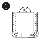
- Position the UWP on the wall. Level and mark hole positions. See Figure 2. Drill holes at marked positions, and then lightly tap supplied wall anchors into wall using a hammer. ‒ If your box contains red anchors, use a 7/32" drill bit. If your box contains yellow anchors, use a 3/16" drill bit.
![]()
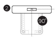
- Pull the door open and insert wires through wiring hole of the UWP. See Figure 3.
![]()
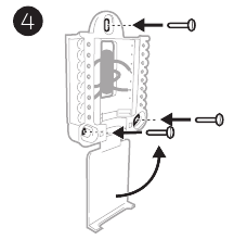
- Place the UWP over the wall anchors. Insert and tighten mounting screws supplied with the UWP. Do not overtighten. Tighten until the UWP no longer moves. Close the door. See Figure 4
![]()
Use 3x supplied screws (#8 1-1/2 for red anchors and #6 1-1/2 for yellow anchors)
Optional Cover Plate installation
Use the Optional Cover Plate when:
- Mounting the thermostat to an electrical junction box
- Or when you need to cover paint gap from the old thermostat.
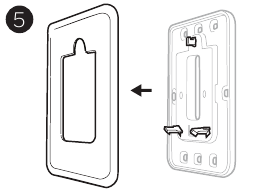
- Separate the Junction Box Adapter from the Cover Plate. See Figure 5.
![]()
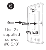
- Mount the Junction Box Adapter to the wall or an electrical box using any of the eight screw holes. Insert and tighten mounting screws supplied with Cover Plate Kit. Do not overtighten. Make sure the Adapter Plate is level. See Figure 6.
![]()
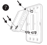
- Attach the UWP by hanging it on the top hook of the Junction Box Adapter and then snapping the bottom of the UWP in place. See Figure 7.
![]()
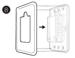
- Snap the Cover Plate onto the Junction Box Adapter. See Figure 8.
![]()
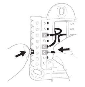
Wiring UWP
Push down on the tabs to put the wires into the inner holes of their corresponding termi nals on the UWP (one wire per terminal) until they are firmly in place. Gently tug on the wires to verify they are secure. If you need to release the wires again, push down the terminal tabs on the sides of the UWP.
This wiring is just an example, yours may vary.
Terminal designations
| Conventional Systems | Heat pump systems | ||
| Terminal | Description | Terminal | Description |
| S/S | Input for a wired indoor, outdoor sensor | S/S | Input for a wired indoor, outdoor sensor |
| Y | Compressor Stage 1 | Y | Compressor Stage 1 |
| Y2 | Compressor Stage 2 | Y2 | Compressor Stage 2 |
| G | Fan Relay | G | Fan Relay |
| C | 24VAC Common wire from secondary side of cooling transformer (if 2 transformers) | C | 24VAC Common wire from secondary side of cooling transformer |
| K* | Connect to K on C-wire adaptor | K* | Connect to K on C-wire adaptor |
| U/U** | Relay for humidifier, dehumidifier, or ventilator | U/U** | Relay for humidifier, dehumidifier, or ventilator |
| A | L/A | Connect to compressor monitor | |
| W | Heat Stage 1 | O/B | Changeover valve for heat pumps |
| W2 | Heat Stage 2 | Aux | Backup Heat |
| E | Emergency Heat | ||
| R | 24 VAC Heating transformer | R | 24 VAC Heating transformer |
| Rc | 24 VAC Cooling transformer | Rc | 24 VAC Cooling transformer |
* The THP9045A1098 C-wire adaptor is used on heat/cool systems when you only have four wires at the thermostat and you need a fifth wire for a common wire. Use the K terminal in place of the Y and G terminals on conventional or heat pump systems to provide control of the fan and the compressor through a single wire—the unused wire then becomes your common wire. See THP9045 instructions for more information.
** See note on Wiring U terminals on the following page.
Setting Slider Tabs
Set R Slider Tab, see Figure 9.

- Use built-in jumper(R Slider Tab) to differentiate between one or two transformer systems.
- If there is only one R wire, and it is connected to theR, Rc, or RH terminal on the old thermostat, set the slider to the up position (1 wire).
- If there is one wire connected to theR terminal and one wire connected to the Rc terminal, set the slider to the down position (2 wires).
Set U Slider Tab, see Figure 10.

- Use built-in jumper (U Slider Tab) for IAQ device.
- When theU Slider Tab is in the down position (2 wires) the U contacts are a dry set of contacts.
- If your IAQ device is powered by the cooling transformer, move theU Slider Tab to the up position (1 wire). When this is done, the lower U terminal is internally jumped to the Rc terminal. In this application, you would hook up one wire from your IAQ device to the upper U terminal and the other to the common side of the cooling transformer. The 1 wire setting is most commonly used when using a fresh air damper for ventilation or using low speed fan for dehumidification.
- See wiring examples on the next page.
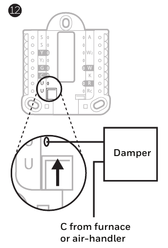
Whole house humidifier, dehumidifier, or ventilator
Using U Slider Tab
- Wired to humidifier, dehumidifier or ventilator with built-in transformer.

- Wired to fresh air damper powered by furnace transformer.
![]()
- Wired to humidifier, ventilator, or damper powered by external transformer

- Wired to low speed fan terminal on HVAC for dehumidification


Wiring
NOTES:
- Use 18- to 22- gauge thermostat wire. Shielded cable is not required.
- Set the R Slider Tab on the UWP to the up position (1 wire) for 1 transformer systems or the down position (2 wires) for 2 transformer systems. See "Setting Slider Tabs".
- Set the U Slider Tab as shown in the diagrams.
Conventional systems
1H/1C System (1 transformer)
R Power
Rc [R+Rc joined by Slider Tab]
Y Compressor contactor
C* 24VAC common
W Heat relay
G Fan relay
1H/1C System (2 transformers)
R Power (heating transformer)
Rc Power (cooling transformer)
Y Compressor contactor
C* 24 VAC common from cooling transformer
W Heat relay
G Fan relay
2H/2C System (1 transformer)
R Power
Rc [R+Rc joined by Slider Tab]
Y Compressor contactor (stage 1)
C* 24VAC common
W Heat relay (stage 1)
G Fan relay
W2 Heat relay (stage 2)
Y2 Compressor contactor (stage 2)
Heat-only System with Fan
R Power
Rc [R+Rc joined by Slider Tab]
C* 24VAC common
W Heat relay
G Fan relay
Cool-only System with Fan
R Power
Rc [R+Rc joined by Slider Tab]
Y Compressor contactor
C* 24VAC common
G Fan relay
Hot Water Relay Panel
R Power
Rc [R+Rc joined by Slider Tab]
W Heat Relay
C* 24VAC common
NOTE: If the panel does not provide 24 volts AC at R and C, set the slider to down position and wire a separate transformer to Rc and C.
* This thermostat requires a C-Wire. If a C-Wire is not available and the system uses Y and G, use C-Wire adapter accessory THP9045A1098.
Power open Zone valve
R Power from transformer
Rc [R+Rc joined by Slider Tab]
W Valve
C* 24VAC common
Series 20 Zone valve
(power open and power closed)
R Power from transformer
Rc [R+Rc joined by Slider Tab]
W Power open valve (usually B)
Y Power close valve (usually W)
C* 24VAC common
NOTE: If the valve uses Y for power close, the thermostat needs to be configured for a radiant heat system without cooling.
Heat pumps systems
1H/1C Heat Pump System
R Power
Rc [R+Rc joined by Slider Tab]
Y Compressor contactor
C* 24VAC common
O/B Changeover valve
G Fan relay
2H/1C Heat Pump System
R Power
Rc [R+Rc joined by Slider Tab]
Y Compressor contactor
C* 24VAC common
O/B Changeover valve
G Fan relay
Aux Auxiliary heat**
E Emergency heat relay**
L Heat pump fault input
2H/2C Heat Pump System
R Power
Rc [R+Rc joined by Slider Tab]
Y Compressor contactor (stage 1)
C* 24VAC common
O/B Changeover valve
G Fan relay
Y2 Compressor contactor (stage 2)
L Heat pump fault input
3H/2C Heat Pump System
R Power
Rc [R+Rc joined by Slider Tab]
Y Compressor contactor (stage 1)
C* 24VAC common
O/B Changeover valve
G Fan relay
Aux Auxiliary heat**
E Emergency heat relay**
Y2 Compressor contactor (stage 2)
L Heat pump fault input
NOTE: Do NOT use W for heat pump applications. Auxiliary heat must wire to AUX or E.
* This thermostat requires a C-Wire. If a C-Wire is not available and the system uses Y and G, use C-Wire adapter accessory THP9045A1098.
** If you do not have separate wires for the Aux and E terminals, connect the wire to the Aux terminal.
Mounting thermostat

- Push excess wire back into the wall opening.
- Close the UWP door. It should remain closed without bulging.
- Align the UWP with the thermostat, and push gently until the thermostat snaps in place.
Note: If you used the Optional Cover Plate shown, remove the gray trim ring from the thermostat before step 3. Then align the thermostat with cover plate and push gently until the thermostat snaps into place.
Note: If needed, gently pull to remove the thermostat from the UWP
Installer setup
The display will walk you through equipment setup, connecting to wireless sensors and connecting to Wi-Fi.
The final step in the setup is a place you can enter your company name and contact information as well as your Contractor PRO™ number.
That contact information will be displayed with alert or reminder messages to keep you connected to your customer.
Enter your company's Contractor PRO™ account number to participate in periodic promotions. Earn incentives such as bonus points for every T10 Pro Smart thermostat you install during eligible promotional periods. Your account number is an 8-digit number that includes a leading zero (example 01234567).
For questions on this bonus or membership to the Contractor PRO™ loyalty program, contact us at 1-800-919-4835 or contractorpro@resideo.com.
Sensor installation
(Optional C7189R2002-2 wireless sensor 2-pack sold separate. Up to 20 sensors max per thermostat)
- Remove white cover from grey base and Insert (2) AAA Alkaline batteries in the sensor.

- Open the menu.
- Tap "Devices & Sensors."
- Tap "Add."
- Follow the on-screen instructions.

- Snap the sensor onto the wall-plate.
- Adhere the included command strip to theWALL wall-plate. Then adhere the sensor to the wall. Level sensor for appearance. (See the sensor instructions for proper placement.)


Apple® HomeKit™ Setup

- Touch Menu icon at the bottom of the T10 home screen.
- Scroll down and select "Connect HomeKit".
- Use the Apple Home App and select "Add Accessory". Scan the code shown on your thermostat with your phone.
- Follow the instructions on your phone.
How to use your thermostat
The screen will wake up by pressing the center area of the displayed temperature.

How to use Priority
Priority creates an average temperature in your home based on specific rooms. This allows you to prioritize comfort where you want it.

How to find more options
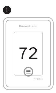
- Touch the menu button.
![]()
- Scroll up and down for more options.
![]()
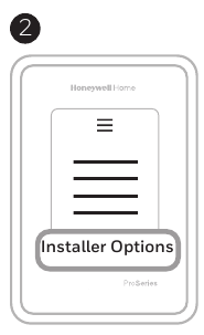
Menu options include
Installer Setup
- System type
- IAQ control (hum, dehum, vent) reminders
Installer Test
- Turn on heat, cool, or IAQ equipment
Devices & Sensors
- View, add, or remove RedLINK indoor sensors
- Identity wireless sensors
- Add wireless sensors Device Information
Thermostat Information
- MAC ID number
- IP address
- Date code
- Model number
- Build date
- Stat app
- Firmware version
- Stat app boot #
- Hardware
Dealer Information
Finding date code (pass code) for installer setup.
Open the Menu icon, and choose Thermostat Information. Write down date code.
Alerts and notifications
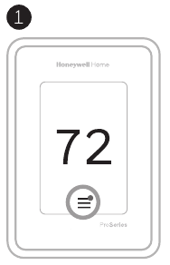
- The red dot above the Menu icon indicates an active alert or notification. Touch theMenu icon to view active Alerts & Notifications.
![]()
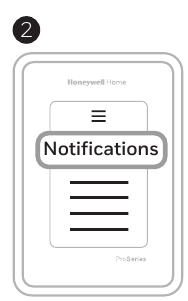
- TouchNotifications to open this menu.
![]()
- Touch the alert message to see more information about the alert.


Troubleshooting
Screen is blank |
|
Screen is difficult to read |
|
Heating or cooling system does not respond |
|
Temperature settings do not change | Make sure heating and cooling temperatures are set to acceptable ranges:
|
| "Cool On" or "Heat On" is flashing |
|
Aux heat runs in cooling |
|
Cool runs with a call for heat |
|
Heat runs with cooling |
|
Sensor will not connect |
|
Specifications
Temperature Ranges
Heat: 40°F to 90°F (4.5°C to 32.0°C)
Cool: 50°F to 99°F (10.0°C to 37.0°C)
Operating Ambient Temperature
32°F to 120°F (0°C to 48.9°C)
Shipping Temperature
-20°F to 120°F (-28.9°C to 48.9°C)
Operating Relative Humidity
5% to 90% (non-condensing)
Humidity setting range
10% to 60% RH.
Dehumidity setting range
25% to 80% RH.
Electrical Ratings
| Terminal | Voltage (50/60Hz) | Running Current |
| W Heating | 20-30 Vac | 0.02-1.0 A |
| (Powerpile) | 750 mV DC | 100 mA DC |
| W2 (Aux) Heating | 20-30 Vac | 0.02-1.0 A |
| E Emergency Heat | 20-30 Vac | 0.02-0.5 A |
| Y Compressor Stage 1 | 20-30 Vac | 0.02-1.0 A |
| Y2 Compressor Stage 2 | 20-30 Vac | 0.02-1.0 A |
| G Fan | 20-30 Vac | 0.02-0.5 A |
| O/B Changeover | 20-30 Vac | 0.02-0.5 A |
| L/A Input | 20-30 Vac | 0.02-0.5 A |
| U | 20-30 Vac | 0.02-0.5 A |
Power Consumption 3 VA
Physical Dimensions in inches (mm) (H x W x D)
T10 PRO Smart Thermostat:
4.9" x 3.7" x 0.93" (125.4 x 94.1 x 23.68)
UWP Mounting System (included):
2-9/32" x 2-13/64" x 2-43/64" (58 x 56 x 10)
Cover Plate – (THX321WFS2001W):
5-11/64" x 5-1/2" x 11/16" (131 x 140 x 17.5)
Cover Plate – (THX321WF2003W):
6-7/64" x 6-7/64" x 9/32" (155 x 155 x 7)
C7189R2002 wireless indoor sensor- ordered separate
2.6" X 2.6" X.77" (66.25 x 66.25 x 19.7)

ELECTRICAL HAZARD
Can cause electrical shock or equipment damage. Disconnect power before beginning installation.

EQUIPMENT DAMAGE HAZARD
Compressor protection is bypassed during testing. To prevent equipment damage, avoid cycling the compressor quickly.
MERCURY NOTICE
If this product is replacing a control that contains mercury in a sealed tube, do not place the old control in the trash. Contact your local waste management authority for instructions regarding recycling and proper disposal.
ELECTRONIC WASTE NOTICE
The product should not be disposed of with other household waste. Check for the nearest authorized collection centers or authorized recyclers. The correct disposal of end-of-life equipment will help prevent potential negative consequences for the environment and human health.
Use of the Works with Apple badge means that an accessory has been designed to work specifically with the technology identified in the badge and has been certified by the developer to meet Apple performance standards. Apple is not responsible for the operation of this device or its compliance with safety and regulatory standards.
References
Download manual
Here you can download full pdf version of manual, it may contain additional safety instructions, warranty information, FCC rules, etc.
Download Honeywell Home T10 Pro, THX321WFS2001W, THX321WF2003W Manual


