Gigabyte BRIX GB-BRU5-225H / GB-BRU7-255H Manual
System Information
Installation Precautions
The system contain numerous delicate electronic circuits and components which can become damaged as a result of electrostatic discharge (ESD). Prior to installation, carefully read the user manual and follow these procedures:
- Prior to installation, do not remove or break motherboard S/N (Serial Number) sticker or warranty sticker provided by your dealer. These stickers are required for warranty validation.
- Always remove the AC power by unplugging the power cord from the power outlet before installing or removing the motherboard or other hardware components.
- When connecting hardware components to the internal connectors on the motherboard, make sure they are connected tightly and securely.
- When handling the motherboard, avoid touching any metal leads or connectors.
- It is best to wear an electrostatic discharge (ESD) wrist strap when handling electronic components such as a motherboard, CPU or memory. If you do not have an ESD wrist strap, keep your hands dry and first touch a metal object to eliminate static electricity.
- Prior to installing the motherboard, please have it on top of an antistatic pad or within an electrostatic shielding container.
- Before unplugging the power supply cable from the motherboard, make sure the power supply has been turned off.
- Before turning on the power, make sure the power supply voltage has been set according to the local voltage standard.
- Before using the product, please verify that all cables and power connectors of your hardware components are connected.
- To prevent damage to the motherboard, do not allow screws to come in contact with the motherboard circuit or its components.
- Make sure there are no leftover screws or metal components placed on the motherboard or within the computer casing.
- Do not place the computer system on an uneven surface.
- Do not place the computer system in a high-temperature environment.
- Turning on the computer power during the installation process can lead to damage to system components as well as physical harm to the user.
- If you are uncertain about any installation steps or have a problem related to the use of the product, please consult a certified computer technician.
Product Specifications
 NOTE:
NOTE:
We reserve the right to make any changes to the product specifications and product-related information without prior notice.
 System Dimension System Dimension | Š 112.6 x 119.4 x 34.4 mm, 0.5 L Š Motherboard size: 105 x 114.49 mm |
 CPU CPU | GB-BRU7-255H Intel® Core™ Ultra 7 Processor 255H 16C, 6P+8E+2LPE, 28W GB-BRU5-225H Intel® Core™ Ultra 5 Processor 225H 14C, 4P+8E+2LPE, 28W |
 NPU NPU | Š Intel® AI Boost NPU up to 13 TOPS |
 Memory Memory |
|
 LAN LAN | Š 2.5GbE LAN (Intel® I226V) |
 Graphics Graphics | GB-BRU7-255H Intel® Arc™ 140T GPU GB-BRU5-225H Intel® Arc™ 130T GPU (Intel® Arc™ Graphics requires using 2 x SO-DIMM / CSO-DIMM dual channel memory) |
 Wifi Card Wifi Card | Š RTL8922AE Š Wi-Fi 7; 802.11 a/b/g/n/ac WLAN 2T2R with Bluetooth 5.2 |
 Audio Audio | Š Realtek ALC245 |
 Expansion Slots Expansion Slots | Š 1 x M.2 2280 slot for SSD (PCIe Gen 4x4) (PCIe Gen 5x4, ready design) Š 1 x M.2 2280 slot for SSD (PCIe Gen 4x4 + SATA) Š 1 x M.2 2230 slot for WiFi + Bluetooth card |
| HDMI Resolution (Max.) | Š HDMI 2.1 Š Support 4K@60P HDR10 |
| VESA | Š VESA Mounting Hole Š Supports 75 x 75 and 100 x 100 mm |
 Front I/O |
|
 Rear I/O |
|
 Left I/O |
|
 Power Supply |
|
 Support OS |
|
 Environment |
|
Package Contents
GB-BR Bare-bone
- NOT Include any of the following: M.2 (2280), SO-DIMM/CSO-DIMM memory
100W Adapter & Power Cord (20 Vdc, 5.0A)
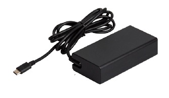
The product should be used with the included power cord. The included power cord should not be used with other products.
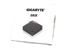
Quick Start Guide
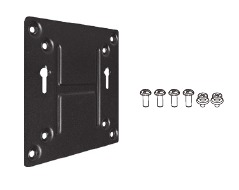
VESA Mount Bracket & 6 x Screws
Wire Clamp Screw

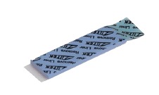
DDR PAD
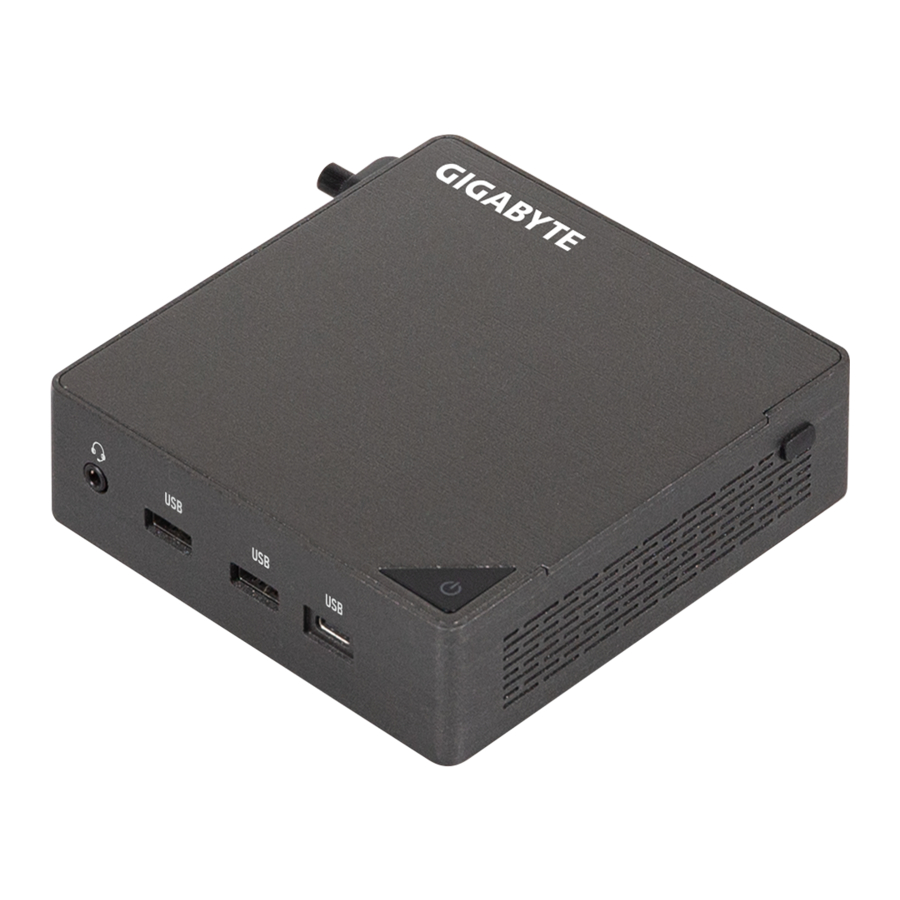
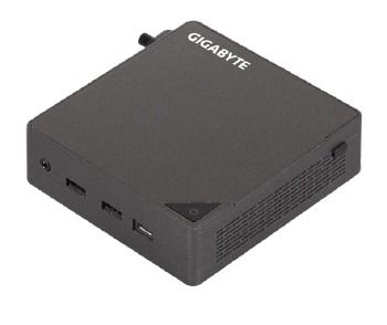
System Appearance
Getting Familiar with Your Unit
Top View

- Power Button
Front View

- Headset
- USB 3.2 Gen2 Type A (10Gbps)(5V/0.9A)
- USB 3.2 Gen2 Type C (10Gbps)(5V/3A)
Rear View

- RJ-45 (10/100/1000/2500Mbps)
- HDMI 2.1 4K(4096 x 2160) 60Hz*2
- USB 2.0 Type A (480Mbps)(5V/0.5A)
- USB4 (40Gbps)(5V/3A)
- PD IN (20V/5A)
- USB 3.2 Gen2 Type A (10Gbps)(5V/0.9A)
Left View

- Vent Hole
- Kensington Lock Slot
Right View

- Vent Hole
- Wire Clamp Screw Hole
Bottom View

- VESA Screw Hole
PIN Definition

- Wi-Fi Connector
- M.2 M Key 2280 SSD slot (PCIe 4.0 x4 or SATA)
- M.2 M Key 2280 SSD slot (PCIe 4.0 x4) (PCIe 5.0 x4, ready design)
- DDR SO-DIMM / CSO-DIMM slots
NOTE!
Wireless module inclusion may vary based on local distribution.
System Hardware Installation
 Pre-installation Instructions
Computer components and electronic circuit boards can be damaged by electrostatic discharge. Working on computers that are still connected to a power supply can be extremely dangerous. Follow the simple guidelines below to avoid damage to your computer or injury to yourself.
- Always disconnect the computer from the power outlet whenever you are working inside the computer case.
- If possible, wear a grounded wrist strap when you are working inside the computer case. Alternatively, discharge any static electricity by touching the bare metal system of the computer case, or the bare metal body of any other grounded appliance.
- Hold electronic circuit boards by the edges only. Do not touch the components on the board unless it is necessary to do so. Do not flex or stress the circuit board.
- Leave all components inside the static-proof packaging until you are ready to use the component for the installation.
Removing the Bottom Cover
Before you remove the bottom cover
- Make sure the system is not turned on or connected to AC power.
Follow these instructions to remove/install the Bottom Cover:
- Unscrew and remove the bottom cover from system.

- Reinstall the bottom cover to system.


Installing the M.2 SSD

Failure to properly turn off the system before you start installing components may cause serious damage.
Follow these instructions to Install the M.2 SSD:

- Carefully insert the M.2 SSD into slot.
- Push down until the M.2 SSD click into place.
- Make sure the M.2 clip is properly secured to the M.2 SSD.
NOTE!
The illustrations of the M.2 SSD installation shown are for reference only. Please follow the installation steps of actual purchased.
Installing the Memory
Read the following guidelines before you begin to install the memory:
- Make sure that the system supports the memory. It is recommended that memory of the same capacity, brand, speed, and chips be used.
- Always turn off the computer and unplug the power cord from the power outlet before installing the memory to prevent hardware damage.
- Memory modules have a foolproof design. A memory module can be installed in only one direction. If you are unable to insert the memory, switch the direction.
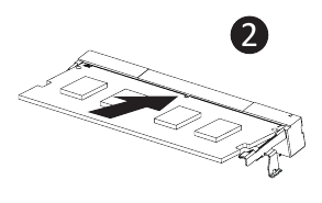
Follow these instructions to Install the Memory(SO-DIMM/CSO-DIMM DDR5):
- When using the following DDR specifications, please apply the DDR PAD to the motherboard.

- Carefully insert SO-DIMM/CSO-DIMM memory modules.
![]()
- Push down until the modules click into place.


NOTE! Please refer to the QVL. DDR5 5600 48 GB and above need to apply DDR PAD.
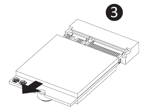
Remove the Wireless Module
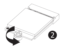
Follow these instructions to remove the WiFi Module:
- Disconnect the two antennas by manually lifting off the clips that hold them in place.

- Remove the screw in the middle.
![]()
- Carefully pull the wireless module from the slot.
![]()

BIOS Setup
USB Power On Function
Allows Device Power-on Via USB. Useful When Mounted Behind a Display or TV
Follow these instructions to enable USB Power On:

- Press "Del" during device start up to enter BIOS.
- Select "Chipset" from the menu.
- Manually configure "USB S5 Wakeup Support" settings to "Enable".
- Press F4 to Save and Exit.
Satety and Regulatory Information
- This product must be grounded with the plug on the adapter's power cord connected to a power socket with a grounding connection. Risk of explosion if the battery is replaced with an incorrect type. Batteries should be recycled where possible. Disposal of used Batteries, must be in accordance with local environmental regulations.
- Before you open chassis to exchange an internal component, you need to power off the device and let the device cool down at least 10 minutes.
- Failure to use the included Model GB-BR Power Adapter may violate regulatory compliance and may expose the user to safety hazards.
Conventions
The following conventions are used in this user's guide:
| | NOTE! Gives bits and pieces of additional information related to the current topic. |
| |  Gives precautionary measures to avoid possible hardware or software problems. |
 | Alerts you to any damage that might result from doing or not doing specific actions. |
Symbol Statement

Hot Surface. Do not touch.
Support
Please visit https://www.gigabyte.com/support-downloads/customer-service to find your BRIX warranty information from the drop down list, or by clicking on the map. You will then be directed to the corresponding page for your region.
- For a list of tested memory, M.2 SSD, wireless adapters and OS supported, go to:https://www.gigabyte.com
- To download the latest drivers and BIOS updates, go tohttps://www.gigabyte.com:
- For product support, go tohttps://www.gigabyte.com:
Download manual
Here you can download full pdf version of manual, it may contain additional safety instructions, warranty information, FCC rules, etc.
Download Gigabyte BRIX GB-BRU5-225H / GB-BRU7-255H Manual

